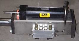
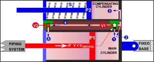
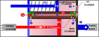
Most hydraulic snubbers have a piston which is relatively unconstrained in motion at low displacement rates. At high displacement rates the piston “locks up”, that is, the force required to move the piston increases substantially, usually as a result of the closing of a valve.
Some of the features include:
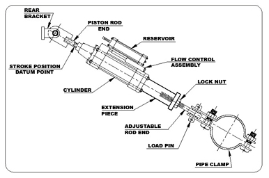
• External pressurized hydraulic reservoir for positioning flexibility in any spatial orientation.
• Allows free thermal movement of piping under normal operations.
• Restrains shock loading, both in tension and compression.
• System’s movement is controlled by a flow control device.
Standard Sizes of PT&P Hydraulic Snubbers
| Bore (in.) | Rod Diameter (in.) | Max Recom. Loads (lb.) |
| 1.5 | 1 | 3000 |
| 2.5 | 1.75 | 10000 |
| 3.25 | 2 | 20000 |
| 4 | 2.5 | 30000 |
| 5 | 2 | 50000 |
| 6 | 2.5 | 70000 |
| 8 | 3.5 | 130000 |
PT&P offers seven sizes with cylinder bores of 1 1/2 to 8 inches. These units have a normal load range of 3,000 lbs to 130,000 lbs. All are made to include reservoirs in 6, 12, or 18 inch strokes. Snubbers, as they are sometimes referred to, are also available with remote reservoirs.
Application
Designed for use on piping systems or equipment where restrained thermal movement must be permitted during normal operation, but rigid restraint is required during sudden dynamic events. These units allow slow thermal expansion while automatically locking to resist impulsive or cyclic disturbances.
They are commonly used to prevent structural damage caused by earthquakes, flow transients, or wind loads. Standard configurations accommodate typical system conditions, while special settings are available to absorb continuous thrust forces, such as those generated by safety valve discharge or pipe rupture events.
Please specify the mounting orientation (vertical or horizontal) when ordering to ensure optimal performance of the unit.
Note: The unit is not effective against low-amplitude, high-frequency vibration.
Ordering
Please specify figure no., cylinder size, stroke, load, cold, and hot pistons settings, and piston end option. If clamp is required, please specify nominal pipe size, or special O.D. and clamp material. Specification or description of any additional optional features or special settings is required.
Dimensions
| Cylinder Size | Stroke (in.) | A | B Min. | C Min. | C Max. | Max. Recom. Normal Load (lb.) |
| 1 1/2 | 6 | 2 1/6 | 1 5/8 | 15 1/2 | 20 1/2 | 3000 |
| – | 12 | – | – | 19 1/2 | 29 1/2 | – |
| – | 18 | – | – | 19 1/2 | 29 1/2 | – |
| 2 1/2 | 6 | 2 1/2 | 2 1/4 | 15 7/8 | 20 7/8 | 10000 |
| – | 12 | – | – | 19 1/2 | 29 1/2 | – |
| – | 18 | – | – | 19 1/2 | 29 1/2 | – |
| 3 1/4 | 6 | 3 1/4 | 3 | 17 5/8 | 22 5/8 | 20000 |
| – | 12 | – | – | 22 5/8 | 32 5/8 | – |
| – | 18 | – | – | 22 5/8 | 32 5/8 | – |
| 4 | 6 | 4 | 3 3/4 | 19 1/2 | 24 1/2 | 30000 |
| – | 12 | – | – | 24 1/2 | 34 1/2 | – |
| – | 18 | – | – | 24 1/2 | 34 1/2 | – |
| 5 | 6 | 5 1/18 | 4 1/2 | 21 | 26 | 50000 |
| – | 12 | – | – | 26 | 36 | – |
| – | 18 | – | – | 26 | 36 | – |
| 6 | 6 | 5 3/4 | 5 1/2 | 23 5/8 | 28 5/8 | 70000 |
| – | 12 | – | – | 28 5/8 | 38 5/8 | – |
| – | 18 | – | – | 28 5/8 | 38 5/8 | – |
| 8 | 6 | 7 1/4 | 6 | 28 7/8 | 33 7/8 | 130000 |
| – | 12 | – | – | 33 7/8 | 43 7/8 | – |
| – | 18 | – | – | 33 7/8 | 43 7/8 | – |
*Loads must not be applied outside a 10° included angle cone of action to the pipe clamp axis w/o special authorization
E-takeout for Fig. 2100 Hydraulic Snubbers and Sway Strut Assemblies
| Pipe Size | 1 1/2 | 2 1/2 | 3 1/4 | 4 | 5 | 6 | 8 |
|
3/4
|
2 7/16 | – | – | – | – | – | – |
|
1
|
2 9/16 | – | – | – | – | – | – |
|
1 1/4
|
2 11/16 | – | – | – | – | – | – |
|
1 1/2
|
4 1/8 | – | – | – | – | – | – |
|
2
|
5 1/8 | 5 | 6 3/8 | 6 3/8 | – | – | – |
|
2 1/2
|
5 3/8 | 6 1/2 | 7 | 7 1/2 | 8 1/8 | – | – |
|
3
|
5 15/16 | 7 | 7 | 7 1/2 | 8 3/8 | – | – |
|
4
|
6 1/2 | 7 | 7 1/4 | 7 1/4 | 8 3/8 | – | – |
|
5
|
7 | 7 | 7 3/4 | 7 3/4 | 9 1/8 | – | – |
|
6
|
8 9/16 | 8 9/16 | 9 1/4 | 9 1/4 | 10 | 11 | – |
|
8
|
9 9/16 | 9 9/16 | 10 1/8 | 10 1/8 | 11 1/4 | 12 | – |
|
10
|
10 7/16 | 10 7/16 | 11 3/8 | 11 3/8 | 12 3/4 | 14 1/4 | 15 |
|
12
|
– | 11 4/9 | 12 4/7 | 12 4/7 | 13 7/8 | 15 | 15 3/4 |
|
14
|
– | 12 11/18 | 13 1/2 | 13 1/2 | 14 1/2 | 15 | 16 1/2 |
|
16
|
– | 13 2/3 | 14 7/8 | 14 7/8 | 15 1/4 | 16 | 17 1/2 |
|
18
|
– | 14 11/16 | 15 1/2 | 15 1/4 | 16 3/4 | 16 3/4 | 18 1/2 |
|
20
|
– | 15 7/8 | 15 7/8 | 16 1/2 | – | – | – |
|
24
|
– | 17 7/8 | 17 7/8 | 19 5/16 | 20 | 22 | 22 |
|
30
|
– | 23 3/8 | 23 3/8 | 23 3/4 | 24 1/4 | 25 | 26 1/4 |
|
36
|
– | 28 3/4 | 28 3/4 | 28 3/4 | 30 3/4 | 32 3/4 | 32 3/4 |
 |
 |
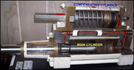
| Schematic of Hydraulic Snubber under normal conditions |
Schematic of Hydraulic Snubber under locked conditions |
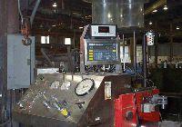
Hydraulic Snubber Test Machine
The Hydraulic Snubber Test Machine is designed to perform functional testing of hydraulic snubbers. It features a test bed configuration similar to the STADAS machine; however, it is not computer-controlled.
This equipment is capable of performing the standard tests typically required for hydraulic snubbers, including quality control verification and periodic testing conducted as part of plant maintenance programs.
Mechanical snubbers can also be tested on this machine. However, due to the increased complexity of the testing procedure, mechanical snubber testing is generally performed on the STADAS machine, which provides greater automation and control.