Mechanical Snubbers provided by Piping Technology and Products, Inc. have two modes of operation. In passive mode, i.e., motion caused by thermal loads, the resisting mechanism is disengaged and the snubber “free wheels” with very low resistance. In active mode the mechanism is engaged, and the snubber limits the acceleration to a low threshold value. There are other types of mechanical snubbers, but these are the most common ones.
The Mechanical Snubber Assembly
The snubber operates on the principle of limiting the acceleration of any pipe movement to a threshold level of .02 g’s. This is the maximum acceleration that the snubber will permit the piping to see. Should a disturbance attempt to accelerate the pipe in either direction, a braking force will be applied within the snubber of whatever magnitude required to limit the acceleration to a value less than .02 g’s. At the same time, thermal expansion, being a gradual movement, is not restricted. A particular feature of the snubber is that at no time does it lock and thereby become a rigid strut. Should a sudden acceleration occur and sustain continuously in one direction, the snubber will apply whatever force is necessary to limit the pipe movement to its present threshold value. The snubber’s performance is independent of the amount of force being applied.
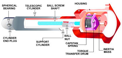
Cross Section View of a Mechanical Snubber
The principle of operation can best be seen in the cross section view above. Two structural telescoping members, colored red and yellow, are connected between the pipe and fixed structure. Within these telescoping tubes is a ball screw and nut which serve to convert the linear telescoping motion, which would occur during a seismic disturbance or thermal changes, to rotational motion of the blue ball screw and drum assembly. This rotational motion is coupled to an inertia mass colored red. The coupling consists of a resilient capstan spring colored orange.
When a disturbance occurs that exceeds the threshold “g” level (.02 g’s), the ball screw and drum attempts to angularly accelerate the inertia mass. The inertial resistance of the mass causes the resilient capstan spring to tighten around a hardened mandrel which is part of the red structural tube. In this manner, a restraining force is applied against rotation of the ball screw, and, in turn, linear telescoping of the silver and red members.
The design of the unit is completely symmetrical, and the same capstan spring will apply this braking action in both the tension and compression loading, which in turn means clockwise or counterclockwise angular acceleration. Therefore, the braking characteristics of the unit in tension and compression are identical.
It can also be noted that when the sudden force is applied, the resisting force is applied by the inertia mass. The inertia mass is mounted to turn freely, and therefore the moment the acceleration drops below the threshold value, it no longer applies a braking force. In additional, the capstan spring is always urging the inertia mass back to an un-braked condition. The net effect is a design which continuously throttles or brakes to limit and control the acceleration. During thermal compensation, the gradual movement, normally associated therewith, is far below the threshold acceleration setting; and therefore, the inertia mass will gradually move without tightening the capstan brake. Should this thermal movement be uneven or jerky as might occur because of a hanger or skid sticking, the unit might momentarily brake, while permitting the pipe movement.
Standard Sizes, Load Rating and Maximum Stroke
| Size | Load Rating | Maximum Stroke |
| MSA – 1/4 | 350 | 4 |
| MSA – 1/2 | 650 | 2 1/2 |
| MSA – 1 | 1500 | 4 |
| MSA – 3 | 6000 | 5 |
| MSA – 10 | 15000 | 6 |
| MSA – 35 | 50000 | 6 |
| MSA – 100 | 120000 | 6 |
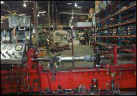
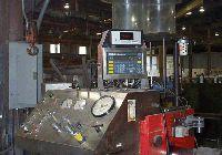
PT&P has two test machines specifically designed for testing snubbers for piping applications, one for routine testing of hydraulic snubbers, and a more sophisticated machine that can perform a wide range of tests on both hydraulic and mechanical snubbers.
PT&P’s STADAS Snubber Test Machine
The STADAS is a trailer mounted snubber test machine manufactured by Paul-Munroe Inc., California. This computer controlled, hydraulic test machine is used to test the performance of mechanical and hydraulic snubbers ranging in size from 150 lb. to 135,000 lb. The STADAS may also be used to verify snubber conditions at the point of manufacture, or during an outage (refueling) at the plant site.
The STADAS machine is capable of controlling a test, following any load sequence needed. It can then plot the test results immediately, and save the results to a disk for future reference.
The main frame of the STADAS machine is comprised of two drive cylinders, which supports the snubber being tested. The smaller drive cylinder is used for snubbers rated to 6000 lb., and the large drive cylinder is used for snubbers rated up to 150,000 lb. Each drive cylinder is equipped with an electro-hydraulic servo-valve load cell and connections to the hydraulic system.
PT&P has two test machines specifically designed for testing snubbers for piping applications, one for routine testing of hydraulic snubbers, and a more sophisticated machine that can perform a wide range of tests on both hydraulic and mechanical snubbers.