Industrial piping systems are engineered to precise specifications, but operating conditions rarely hold still. Thermal expansion, structural settlement, and installation variances gradually push pipes out of their designed positions, and when a line sits at the wrong elevation, it carries stress that was never accounted for in the original design. Left unaddressed, that stress shortens service life, increases maintenance frequency, and raises the risk of failure in systems.
Wedge block assemblies, also called shim blocks, are the engineered answer to this problem. These adjustable supports are installed beneath piping to raise, lower, or level the pipe with precision, without requiring structural modification to the surrounding system. They are widely used across refineries, crude oil terminals, petrochemical plants, and heavy process facilities.
This article walks through everything a reader needs to understand about how wedge blocks work, the critical design process, and the value Piping Technology & Products (PT&P) delivers through its solutions.
How a Wedge Block Assembly Works
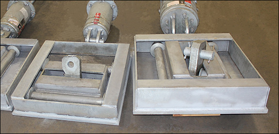
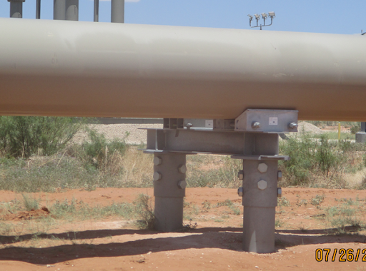
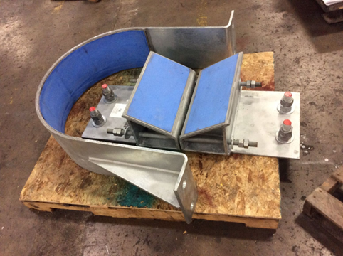
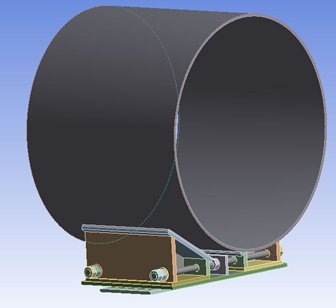
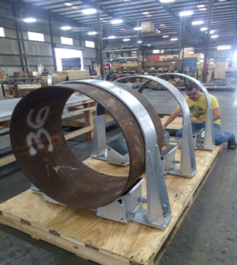
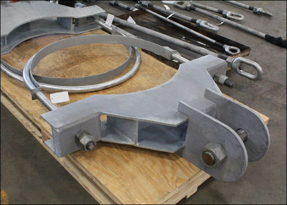
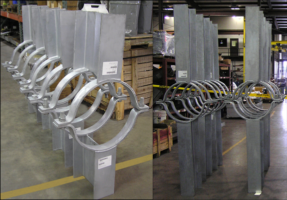
A wedge block assembly consists of two tapered steel blocks supplied as a matched pair, connected by rods and fasteners. The blocks are positioned beneath the pipe at equal distances from the centerline. Because they are tapered, their combined height changes with their lateral position, sliding them inward raises the pipe, and moving them outward lowers it. Once the target elevation is reached, the fasteners are tightened to lock the assembly in place.
Additional components can be specified depending on the system’s requirements:
| Component | Function |
| Hold-down clamps | Fully secure the pipe against movement in all directions |
| Slide plates | Allow axial pipe movement while maintaining vertical support |
| Fasteners and rods | Connect the block pair and lock the set elevation |
This configuration gives field engineers a reliable, repeatable way to correct pipe elevation after installation, without dismantling the support structure or rerouting the line.
Where Wedge Blocks Are Specified
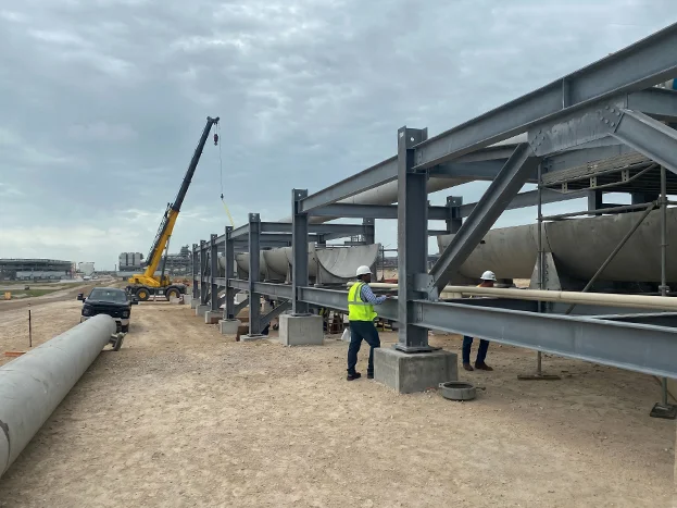
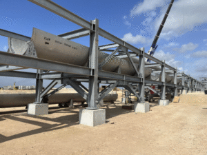
Wedge block assemblies are the right support solution when a fixed support cannot meet the system’s demands. Common conditions that call for them include post-installation elevation correction, misalignment that would transfer damaging stress into the piping if held by a rigid support, systems where axial movement must be accommodated alongside vertical control, and environments where the pipe-to-support interface needs active corrosion management.
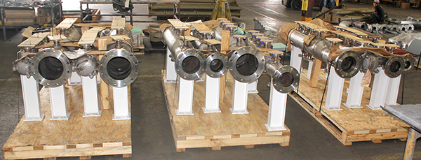
Refineries, crude oil terminals, and petrochemical plants are the most frequent users, primarily because their piping systems carry heavy loads, run at elevated temperatures, and are expected to operate continuously for decades.
Load Capacity and Custom Design
Every assembly is custom-engineered based on the project’s specific requirements, which is why PT&P has been able to deliver assemblies ranging from a few hundred pounds of support capacity all the way up to 84,000 lbs. The design is always derived from the application.
To develop a custom wedge block specification, PT&P’s engineering team requires the following inputs:
| Required Input | Why It Matters |
| Pipe size | Determines block geometry and contact area |
| Desired load rating | Drives structural sizing and liner selection |
| Support location and floor or steel dimensions | Defines the available footprint |
| Line temperature and operating environment | Controls material and liner specifications |
| Required height adjustment range (e.g., 4″ to 8″) | Sets taper angle and travel limits |
| Axial movement requirements | Determines whether slide plates are needed |
Critical Consideration – Temperature and load are the inputs most frequently left incomplete, and both have direct consequences on the final design. If either is uncertain at the time of inquiry, that should be stated upfront, PT&P’s engineers can advise on approaches that preserve design flexibility while project details are confirmed.
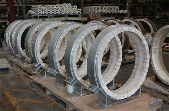
Liner Material Selection
The liner sits at the contact surface between the pipe and the assembly, and it governs friction behavior, vibration response, and corrosion performance in service. Standard PT&P assemblies are rated up to 250°F, and liner selection becomes especially critical in applications approaching or exceeding that threshold.
| Liner Material | Primary Function |
| PTFE Pads | Low-friction interface for systems requiring free axial pipe movement |
| Fabric Pads | Vibration damping at the support interface |
| Vibron Pads | High compressive strength for heavy-load applications |
| Neoprene Pads | High-friction interface to resist axial displacement |
| TPI (Thermoplastic Isolators) | Blocks moisture ingress and eliminates the galvanic corrosion pathway |
| FRP (Fiber-Reinforced Plastic) | Structural strength in chemically aggressive environments |
| Tico Pads | Acoustic isolation combined with vibration attenuation |
Corrosion Mitigation
When a pipe rests on a flat support surface, moisture accumulates in the area of contact between the two materials. In the presence of dissimilar metals, that trapped moisture initiates galvanic corrosion, which progressively attacks both the pipe wall and the support structure from the contact zone outward. Wedge block assemblies reduce this risk because the tapered geometry creates line contact rather than surface contact, significantly limiting the area where moisture can collect.
In corrosion-aggressive environments, coastal locations, chemical plants, and high-chloride service, TPI liners provide an additional layer of protection by breaking the electrical pathway between the pipe and the steel support. Without that pathway, galvanic corrosion cannot initiate regardless of moisture exposure.
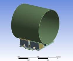
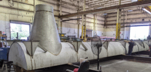
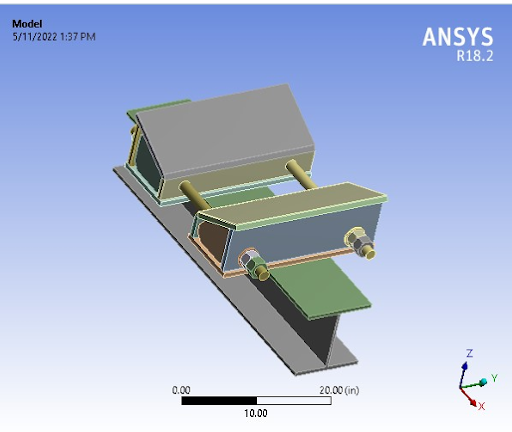
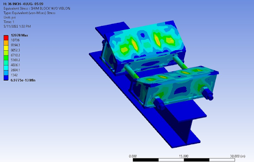
Engineering and Testing Capabilities
While typical vendors rely on off-the-shelf catalogs, we prioritize precision engineering custom to your unique project requirements. PT&P has been designing wedge-type supports for decades, with in-house engineering capability that includes Finite Element Analysis using Ansys for complex and high-load applications. FEA allows the team to model stress distribution, verify load path integrity, and optimize geometry before fabrication begins. Design calculations are available to customers upon request.
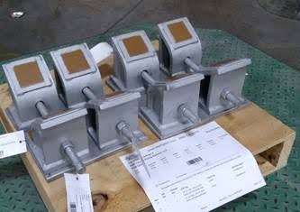
For applications requiring physical verification, our Houston facility conducts load testing to confirm that assemblies perform to their rated capacity under real conditions, providing documented assurance for quality-critical procurement processes.
To learn more about PT&P’s wedge support solutions or discuss project-specific requirements, schedule a consultation with one of our engineering specialists.
Read More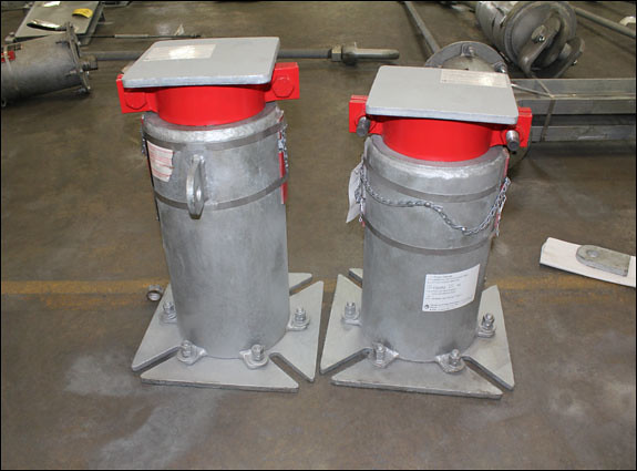

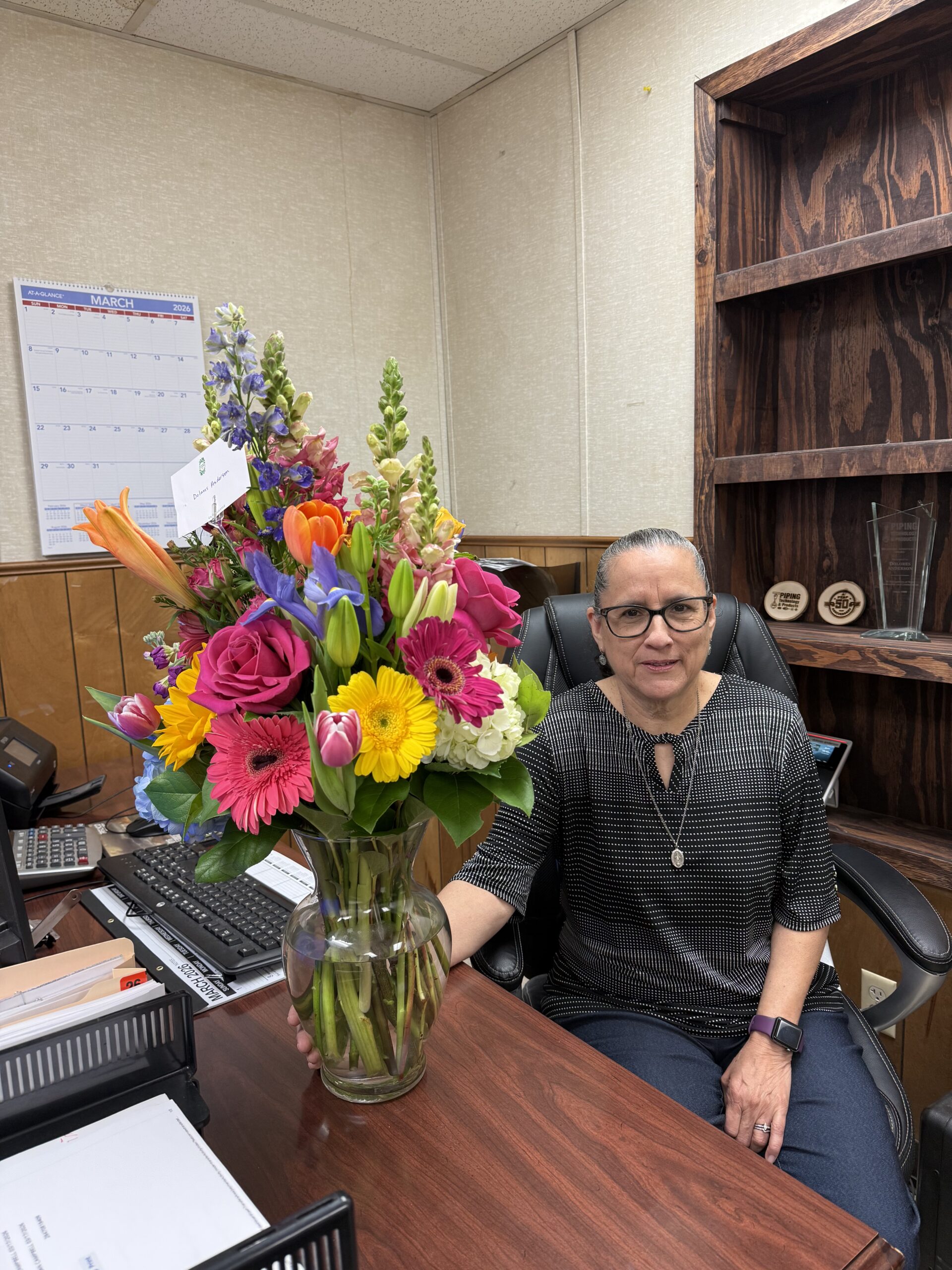 In 1989, when Dolores Anderson walked into Piping Technology & Products’ Long Drive location for her first real job, the accounting office was literally a converted house. The company was smaller, invoices were on paper, and “paperless” wasn’t even a buzzword yet.