Constants use a spring coil (or series of coils) to accommodate pipe movement from the initial (installed) condition to the final (operating) condition of the piping system. For all constant spring supports there is no difference in load and the supported load will remain uniform throughout the deflection cycle.
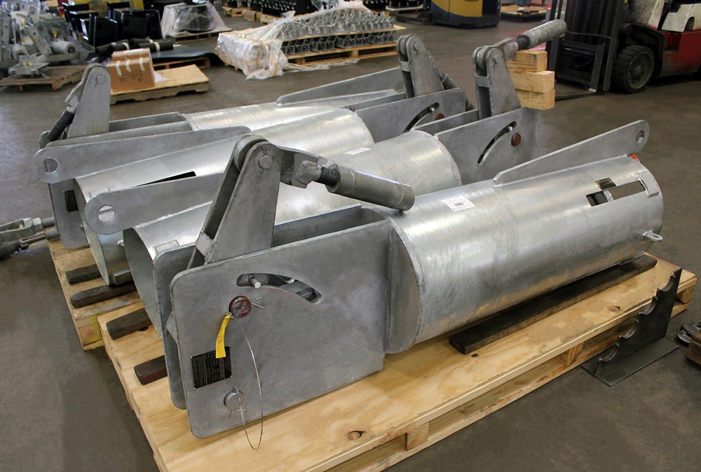
PT&P has set up it's manufacturing to offer an unparalleled set of customization options with minimal impact on delivery timeframes. In addition to our standard (hot-dipped galvanized, neoprene lined springs) constant spring supports, we can customize any material, finish, dimension, load, load adjustment, travel, travel stops, as well as providing sensors for remote monitoring. View more details on how we can customize your constant spring support.
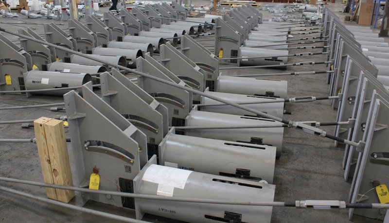
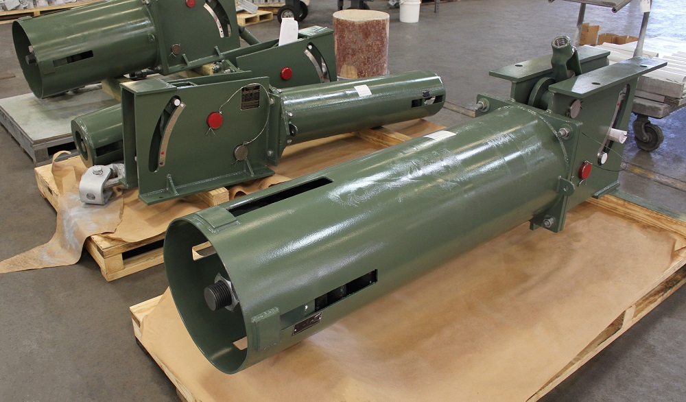
Piping Technology & Products’ constant support hangers are principally used to support pipes and equipment subjected to vertical movement due to thermal expansion at locations where the transfer of stress to other supports or equipment can be critical.
Figure 4: Constant Hangers Types A – E
The constant resistance to a load is achieved by combining a spring coil with a cam which rotates about a main pivot point. The cam is designed such that the distances from the main pivot changes to compensate for the variable resistance during compression of the coil. The MSS standard provides for a tolerance of 6% in the constant load through the travel range. Our constant support hangers are designed per MSS, ANSI, and ASME standards. maximum recommended variation according to MSS standard from the operating load is 25% for variable spring hangers. If the variation exceeds 25%, a constant support hanger should be used.
Caution: Do not force the travel stops.
PT&Ps’ constant support hangers are principally used to support pipes and equipment subjected to vertical movement due to thermal expansion at locations where the transfer of stress to other supports or equipment can be critical. The maximum recommended variation according to MSS standard from the operating load is 25% for variable spring hangers. If the variation exceeds 25%, a constant support hanger should be used. The constant resistance to a load is achieved by combining a spring coil with a cam which rotates about a main pivot point. The cam is designed such that the distances from the main pivot changes to compensate for the variable resistance during compression of the coil. The MSS standard provides for a tolerance of 6% in the constant load through the travel range. Our constant support hangers are designed per MSS, ANSI, and ASME standards.
PIPE STRESS ANALYSIS
Spring Supports sizing is determined by a Pipe Stress Model which assesses the thermal growth and associated stress on the piping, nozzles, etc. The Pipe Stress model determines how the piping can be designed to move and avoid placing under stress on the nozzles to equipment and the piping itself. Having started as a Pipe Stress Engineering company, PT&P has deep experience in Pipe Stress Analysis. We can quote directly from the stress analysis. Beyond the Pipe Stress analysis, we will need elevation, attachment type, and any space constraints. Another issue that comes up from many customers is the need to replace spring supports for which the load information has been lost. For these situations, PT&P has the following solutions:
– Estimate the load based on the pipe and media specification and estimate movement from existing spring support
– Weigh the Piping to determine the load and estimate movement from existing spring support
– Perform a Pipe Stress Analysis to determine exact load and movement. To perform a Pipe Stress Analysis, PT&P will need Isometrics and overall specifications for the line. PT&P is almost always very cost-effective for Pipe Stress Analysis.* If drawings are unattainable or you don’t have access to the ISO drawings, we can perform Laser Scanning on the piping system and generate the drawings.
SIZING CONSTANT SPRING SUPPORTS
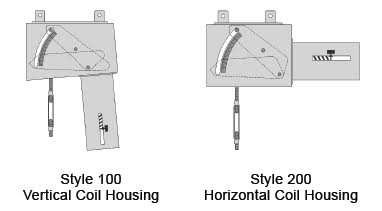
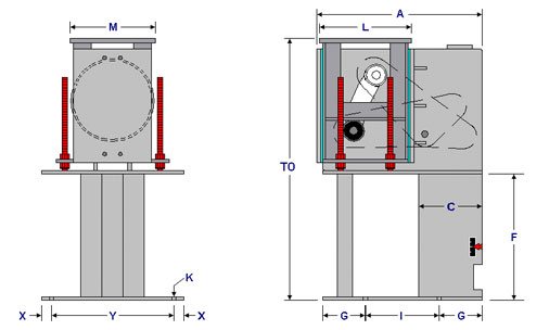
Both constant support styles, style 100 (with a vertical coil housing orientation), style 200 (with a horizontal coil housing orientation), function in the same manner. The key to selecting a constant support style would be the space available for that support above, below and around the piping (see below).
The next step would be to select a support type. Types that support piping from above would be types (A, B, C, D, E, and G), as in the above examples. Types that support piping from below would be types (F and U).
Step 1: Determine The Load: this is the load (installed/operating) of the equipment or piping (including tare / dead weight), which the constant is to support. Cold and hot loads shall be the same.
Step 2: Determine Total Travel: the total travel is the vertical design travel plus the recommended over travel rounded up to the nearest ½ inch. The over travel is a safety margin to allow for the discrepancy between the calculated and actual travel.
The amount of over travel is determined by the method outlined below:
a) For actual travel less than 5 inches, the over travel is 1 inch.
b) For actual travel of 5 inches and over, the over travel is 20% of the actual travel.
Total Travel = Actual Travel + Over Travel
SIZING CONSTANTS (Examples)
Having the total travel and load, the constants are sized per the constant load table. For a given total travel on the top row of the constant load table, select the operating load on the high side under the column. Then move across to the first column to determine the size of the constant support. The following examples will illustrate the procedure.
Example 1 Load = 2,400 lb. Actual Travel = 3.35”
Given an actual travel of 3.35”, which is under 5”, the amount of over travel is 1”. Thus, the total travel is 4 1/2” rounded to the upper 1/2”. For a total travel of 4 1/2” on the top row of the constant load table with a load of 2,456 lb. on the high side (the other load of 2,361 lb. is the low side) gives a constant size of 34 in the first column.
Example 2 Load = 2,400 lb. Actual Travel = 7.10”
Given an actual travel of 7.10”, which is over 5”, the amount of over travel is 1.42”. Thus, the total travel is 9” rounded to the upper 1/2”. For a total travel of 9” on the top row of the constant load table with a load of 2,413 lb. on the high side (the other load of 2,277 lb. is the low side) gives a constant size of 44 in the first column.
PHYSICAL DIMENSIONS OF CONSTANTS
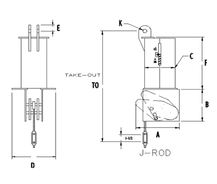
The dimensions for the standard PT&P constants are listed in the following pages per load and travel. The sizing of a constant is independent and not related to its dimensions. To get the proper dimensions, figure (100 or 200), type (A, B, C, D, E, F, G, U), load, total travel, and direction of travel are required. The following example will illustrate the procedure.
Example Figure = 200 Type = C Load = 2,356 lb. Total Travel = 5 1/2” UP
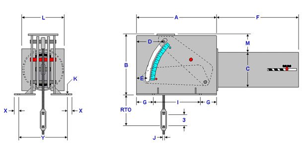
From the Figure 200 Type-C list of tables (see Page 81), the J-Rod and Lug Selection table for a load of 2,356 lb. is 3/4”. From this table under the same column the lug information is provided. For a total travel of 5 1/2 the table titled Total Travel 4 1/2 to 6 (see Page 82) will be used to get the physical dimensions. With a J-Rod of 3/4” and a load of 2,356 lb. which falls in the load range of 766 – 2402, the Rod Take Out (RTO) for up travel is 21 11/16 (15 11/16 + 6, for up travel according to the note at the bottom of the table) and all other physical dimensions are given in the same row. ALL DIMENSIONS ARE IN INCHES UNLESS OTHERWISE NOTED
• RTO – Rod take out for down travel
• F – Maximum length for the load range
• D – J Rod position for down travel
• M – Maximum height for the load range
• E – J Rod position for up travel
• WT – Maximum weight for the load range
J-Rod and Lug Selection
Load (lbs)
0
766
1492
2403
3869
5664
9122
13355
17776
23660
28628
38104
765
1491
2402
3868
5663
9121
13354
17775
23659
28627
38103
46104
J-ROD
1/2
5/8
3/4
1
1 1/4
1 1/2
1 3/4
2
2 1/4
2 1/2
2 3/4
3
K-HOLE
11/16
13/16
15/16
1 1/4
1 1/2
1 3/4
2
2 3/8
2 5/8
2 7/8
3 1/8
3 3/8
H
1 1/2
1 1/2
1 1/2
2
3
3
3
4
4 1/2
4 1/2
4 1/2
5
R
1 1/4
1 1/4
1 1/4
1 1/2
2
2 1/2
2 1/2
3
3
4
4
4
S
7/8
11/16
1 1/4
1 5/8
2
2 3/8
2 5/8
2 7/8
3 1/8
3 3/8
3 5/8
3 7/8
T
1/4
1/4
3/8
1/2
5/8
3/4
3/4
3/4
3/4
1
1
1
W
2 1/2
2 1/2
2 1/2
3
4
5
5
6
6
8
8
8
Total Travel 4 1/2 to 6 Inches
Load Range (lbs)
J-ROD
RTO*
A
B
C
D
E
F
G
I
L
M
WT (lbs)
34 -183
1/2
15 9/16
15 1/4
10 1/4
6 5/8
4 3/8
2
12
2
11 1/4
7
4 3/16
65
184 -765
1/2
16 1/16
16 3/4
11 3/4
8 5/8
5 1/8
2 3/4
15
2 3/4
11 1/4
11 1/2
3 11/16
105
766 - 2402
5/8
15 11/16
16 1/2
11 3/8
8 5/8
4 3/8
2
22
2
12 1/2
11 1/2
3 5/16
220
3/4
15 11/16
2403 - 5663
1
20 3/8
18
13 1/4
8 5/8
5 7/8
3 1/2
33
3 1/4
11 1/2
11 1/2
3 1/2
350
1 1/4
22 3/8
5664 - 12140
1 1/2
24 11/16
21 3/4
16 7/8
12 3/4
7 3/8
5
42
3 3/4
14 1/4
13
4 1/2
975
1 3/4
26 3/16
12141 - 23659
1 3/4
29
26
20 5/8
12 3/4
10 5/16
7 15/16
58
6 5/8
12 3/4
13
7 5/16
1550
2
34
2 1/4
36 1/2
*Rod Take Out (RTO) is for down travel [ Add 6 inches for up travel ]
LOAD ADJUSTMENT
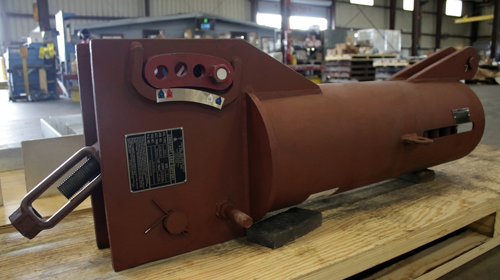
Every constant spring hanger is calibrated in the factory and set to the load specified on the name plate (Figure B). Load adjustment in the field is discouraged as it may significantly change the system.
However, to provide for situations where the supported load is different from the calculated load, the constant spring hangers are equipped with load adjustment capability. The load adjustment capability consists of a load adjustment scale which is used to increase (Figure A) or decrease (Figure C) the load up to 10%. The travel stop pin must be engaged before load adjustment is performed. Adjusting the load to a higher or lower load from the load specified on the nameplate using field load adjustment is approximate. Note that
increasing or decreasing the load by 10% does not affect the total travel.
Under no circumstances should an attempt be made to remove the lock nut and the load adjustment nut from the constant spring hanger.
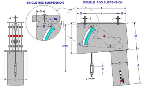
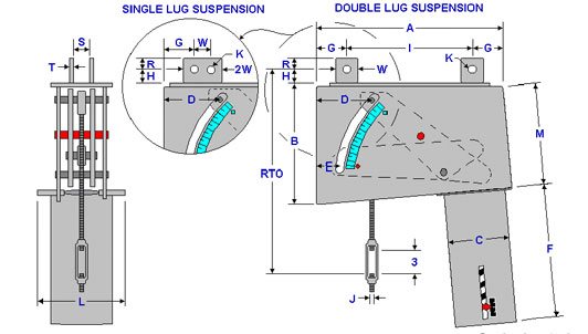
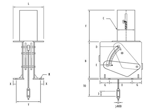
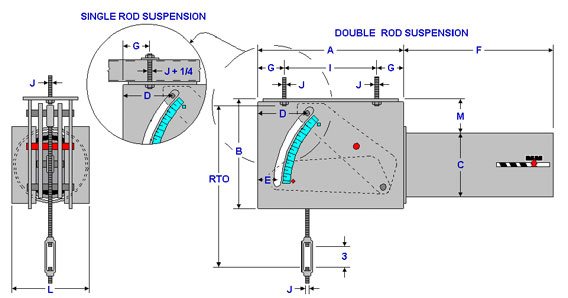
Figure PTP 100-A is a vertical constant suspended from a beam. It can be furnished either with single rod suspension or double rod suspension as shown above. The single rod suspension must be mounted flush to the bottom of the beam where the suspension rod is 1/4 inch thicker than J-Rod. Note that the rod take out (RTO) for the single rod suspension must be adjusted by subtracting 1/4 inch from the values given in the tables below.
ORDERING: Specify figure number, size, type, load, actual travel, total travel and direction of travel. For load and travel not in the tables, please call for dimensions.
Important Notes: ALL DIMENSIONS ARE IN INCHES UNLESS OTHERWISE NOTED.
• RTO – Rod take out for down travel
• D – J-Rod position for down travel
• E – J-Rod position for up travel
• F – Maximum length for the load range
• WT – Maximum weight for the load range
J-Rod Selection
LOAD (lbs)
0 765
766 1491
1492 2402
2403 3868
3869 5663
5664 9121
9122 13354
13355 17775
17776 23659
23660 28627
28628 38103
38104 46104
46105 60000
J-ROD
1/2
5/8
3/4
1
1 1/4
1 1/2
1 3/4
2
2 1/4
2 1/2
2 3/4
3
3 1/4
SUBTRACT 1/4″ OF THE ROD TAKE OUT (RTO) FOR SINGLE ROD SUSPENSION ONLY FROM THE TABLES BELOW
Total Travel 1 1/2 to 4 Inches
LOAD RANGE (lbs)
J-ROD
RTO*
A
B
C
D
E
F
G
I
L
M
WT (lbs)
44 - 243
1/2
13 5/16
16 3/8
9 11/16
6 5/8
3 3/4
2
12
1 7/8
12 5/8
7 5/8
8
65
244 - 1018
1/2
13 5/16
17 3/8
10 1/8
8 5/8
3 3/4
2
15
2 3/8
12 5/8
11 5/8
8 3/8
105
5/8
13 3/16
1019 – 3516
5/8
13 1/4
17 3/8
11 1/8
8 5/8
3 3/4
2
22
2 3/8
12 5/8
11 5/8
9 1/4
225
3/4
13 1/8
1
14 7/8
3517 - 7538
1
15 5/16
20 3/8
12 1/2
8 5/8
4 5/16
2 9/16
33
3 1/2
13 3/8
11 5/8
10 1/8
395
1 1/4
16 1/16
1 1/2
16 1/16
7539 16159
1 1/2
16 15/16
23 9/16
15 3/8
12 3/4
5 9/16
3 7/8
44
4 3/8
14 13/16
18 3/8
12 5/8
1045
1 3/4
18 3/16
2
21 15/16
16160 - 31490
2
24 1/8
24 1/4
18 15/16
12 3/4
6 3/4
5
58
6 1/2
11 1/4
18 3/8
16 1/16
1700
2 1/4
25 7/8
2 1/2
25 5/8
2 3/4
27 3/8
*Rod Take Out (RTO) is for down travel [ Add 4 inches for up travel ]
Total Travel 4 1/2 to 6 Inches
LOAD RANGE (lbs)
J-ROD
RTO*
A
B
C
D
E
F
G
I
L
M
WT (lbs)
34 -183
1/2
13 5/16
18 11/16
12
6 5/8
4 1/2
1 7/8
12
2
14 11/16
7 5/8
10 1/16
75
184 -765
1/2
13 5/16
19 11/16
12 1/2
8 5/8
4 1/2
1 7/8
15
2 3/4
14 3/16
11 5/8
10 1/2
115
766 – 2402
5/8
13 1/4
19 11/16
13 5/8
8 5/8
4 1/2
1 7/8
22
2
15 11/16
11 5/8
11 1/2
230
3/4
13 1/8
2403 – 5663
1
15 5/16
22 13/16
15
8 5/8
5 1/4
2 5/8
33
3 1/4
16 5/16
11 5/8
12 7/16
400
1 1/4
16 1/16
5664 – 12140
1 1/2
16 1/2
25 1/4
17 5/16
12 3/4
5 3/4
3 1/8
44
3 3/4
17 3/4
18 3/8
14 7/16
1035
1 3/4
17 3/4
12141 – 23659
1 3/4
19 15/16
26 5/8
20 7/8
12 3/4
7 1/4
4 5/8
58
6 5/8
13 3/8
18 3/8
17 7/8
1640
2
23 11/16
2 1/4
25 7/16
*Rod Take Out (RTO) is for down travel [ Add 6 inches for up travel ]
Total Travel 6 1/2 to 8 Inches
LOAD RANGE (lbs)
J-ROD
RTO*
A
B
C
D
E
F
G
I
L
M
WT (lbs)
25 – 151
1/2
17 5/16
21 1/4
14 1/2
6 5/8
5 9/16
2
12
2 1/4
16 3/4
7 5/8
12 5/16
90
152 – 632
1/2
17 5/16
22 1/4
15
8 5/8
5 9/16
2
15
2 1/4
17 3/4
11 5/8
12 3/4
130
633 – 1985
1/2
17 3/8
22 1/4
16
8 5/8
5 9/16
2
22
2 1/4
17 3/4
11 5/8
13 5/8
255
5/8
17 1/4
3/4
17 1/8
1986 – 4680
3/4
17 9/16
25 1/8
16 7/8
8 5/8
6 1/16
2 1/2
33
3
19 1/8
11 5/8
14 1/8
420
1
19 5/16
1 1/4
20 1/16
4681 – 10033
1 1/4
20 1/2
27 13/16
19 15/16
12 3/4
6 13/16
3 1/4
44
3 1/2
20 13/16
18 3/8
16 13/16
1090
1 1/2
20 1/2
1 3/4
21 3/4
10034 – 19552
1 3/4
23 1/2
30 3/16
23 7/16
12 3/4
9 5/16
5 3/4
58
4 3/4
20 11/16
18 3/8
20 1/8
1700
2
27 1/4
2 1/4
29
*Rod Take Out (RTO) is for down travel [ Add 8 inches for up travel ]
Total Travel 8 1/2 to 10 Inches
LOAD RANGE (lbs)
J-ROD
RTO*
A
B
C
D
E
F
G
I
L
M
WT (lbs)
21 – 125
1/2
19 5/16
23 3/4
16 5/8
6 5/8
6 5/8
2 1/8
12
2 3/4
18 1/4
7 5/8
14 1/4
100
126 – 522
1/2
19 5/16
24 13/16
16 7/8
8 5/8
6 5/8
2 1/8
15
2 3/4
19 5/16
11 5/8
14 3/8
145
523 – 1640
1/2
19 3/8
24 3/4
18
8 5/8
6 5/8
2 1/8
22
2 3/4
19 1/4
11 5/8
15 3/8
280
5/8
19 1/4
3/4
19 1/8
1641 – 3868
3/4
19 1/8
27 1/4
18 3/4
8 5/8
6 7/8
2 3/8
33
3 1/2
20 1/4
11 5/8
15 3/4
430
1
20 7/8
3869 – 8292
11/4
22 1/16
29 7/8
21 3/4
12 3/4
7 3/8
2 7/8
44
3 1/2
22 7/8
18 3/8
18 3/8
1115
1 1/2
22 1/16
8293 – 16159
1 1/2
22 15/16
31 1/16
23 15/16
12 3/4
8 5/8
4 1/8
58
5 1/4
20 9/16
18 3/8
20 1/2
1685
1 3/4
24 3/16
2
27 15/16
*Rod Take Out (RTO) is for down travel [ Add 10 inches for up travel ]
Total Travel 10 1/2 to 12 Inches
LOAD RANGE (lbs)
J-ROD
RTO*
A
B
C
D
E
F
G
I
L
M
WT (lbs)
17 – 103
1/2
21 5/16
26 3/8
19
6 5/8
7 5/8
2 1/4
12
3 1/4
19 7/8
7 5/8
16 3/8
120
104 – 432
1/2
21 1/4
27 3/8
19 1/2
8 5/8
7 5/8
2 1/4
15
3 1/4
20 7/8
11 5/8
16 3/4
160
433 – 1491
1/2
21 5/16
27 3/8
20 1/8
8 5/8
7 5/8
2 1/4
22
3 1/8
21 1/8
11 5/8
17 5/16
300
5/8
21 3/16
1492 – 3197
3/4
21 1/8
29 3/4
21
8 5/8
7 5/8
2 1/4
33
3 3/8
23
11 5/8
17 13/16
475
1
22 7/8
3198 – 6853
1
23 5/16
32 1/2
23 7/8
12 3/4
8 3/8
3
44
3 5/8
25 1/4
18 3/8
20 5/16
1170
1 1/4
24 1/16
1 1/2
24 1/16
6854 – 13354
1 1/2
24 15/16
33 5/8
26 1/8
12 3/4
9 5/8
4 1/4
58
3 1/4
29 1/8
18 3/8
22 1/2
1710
1 3/4
26 3/16
*Rod Take Out (RTO) is for down travel [ Add 12 inches for up travel ]
Total Travel 12 1/2 to 14 Inches
LOAD RANGE (lbs)
J-ROD
RTO*
A
B
C
D
E
F
G
I
L
M
WT (lbs)
17 – 94
1/2
23 5/16
28 5/8
20 15/16
6 5/8
8 1/2
2 1/8
12
3 3/4
21 1/8
7 5/8
18 1/8
135
95 – 392
1/2
23 5/16
29 11/16
21 1/2
8 5/8
8 1/2
2 1/8
15
3 3/4
22 3/16
11 5/8
18 5/8
180
393 – 1232
1/2
23 5/16
29 11/16
22 11/16
8 5/8
8 1/2
2 1/8
22
3 3/4
22 3/16
11 5/8
19 5/8
330
5/8
23 3/16
1233 – 2906
5/8
23 1/4
32 5/16
23
8 5/8
8 3/4
2 3/8
33
3 3/4
24 13/16
11 5/8
19 9/16
510
3/4
23 1/8
1
24 7/8
2907 – 6230
1
25 5/16
34 3/4
26 1/16
12 3/4
9 1/4
2 7/8
44
4 1/4
26 1/4
18 3/8
22 5/16
1225
1 1/4
26 1/16
1 1/2
26 1/16
6231 – 12140
1 1/2
26 1/2
35 1/2
27 13/16
12 3/4
10
3 5/8
58
3 3/4
28
18 3/8
24
1755
1 3/4
27 3/4
*Rod Take Out (RTO) is for down travel [ Add 14 inches for up travel ]
<!–
J-Rod Selection
LOAD (lbs)
0
765
766
1491
1492
2402
2403
3868
3869
5663
5664
9121
9122
13354
13355
17775
17776
23659
23660
28627
28628
38103
38104
46104
46105
60000
J-ROD
1/2
5/8
3/4
1
1 1/4
1 1/2
1 3/4
2
2 1/4
2 1/2
2 3/4
3
3 1/4
Total Travel 1 1/2 to 4 Inches
LOAD RANGE (lbs)
J-ROD
RTO*
A
B
C
D
E
F
G
I
L
M
WT (lbs)
44 -243
1/2
13 5/16
16 3/8
9 11/16
6 5/8
3 3/4
2
12
1 7/8
12 5/8
7 5/8
8
65
244 – 1018
1/2
13 5/16
17 3/8
10 1/8
8 5/8
3 3/4
2
15
2 3/8
12 5/8
11 5/8
8 3/8
105
5/8
13 3/16
1019 – 3516
5/8
13 1/4
17 3/8
11 1/8
8 5/8
3 3/4
2
22
2 3/8
12 5/8
11 5/8
9 1/4
225
3/4
13 1/8
1
14 7/8
3517 – 7538
1
15 5/16
20 3/8
12 1/2
8 5/8
4 5/16
2 9/16
33
3 1/2
13 3/8
11 5/8
10 1/8
395
1 1/4
16 1/16
1 1/2
16 1/16
7539 – 16159
11/2
16 15/16
23 9/16
15 3/8
12 3/4
5 9/16
3 7/8
44
4 3/8
14 13/16
18 3/8
12 5/8
1045
1 3/4
18 3/16
2
21 15/16
16160 – 31490
2
24 1/8
24 1/4
18 15/16
12 3/4
6 3/4
5
58
6 1/2
11 1/4
18 3/8
16 1/16
1700
2 1/4
25 7/8
2 1/2
25 5/8
2 3/4
27 3/8
*Rod Take Out (RTO) is for down travel [ Add 4 inches for up travel ]
Total Travel 4 1/2 to 6 Inches
LOAD RANGE (lbs)
J-ROD
RTO*
A
B
C
D
E
F
G
I
L
M
WT (lbs)
34 -183
1/2
13 5/16
18 11/16
12
6 5/8
4 1/2
1 7/8
12
2
14 11/16
7 5/8
10 1/16
75
184 -765
1/2
13 5/16
19 11/16
12 1/2
8 5/8
4 1/2
1 7/8
15
2 3/4
14 3/16
11 5/8
10 1/2
115
766 – 2402
5/8
13 1/4
19 11/16
13 5/8
8 5/8
4 1/2
1 7/8
22
2
15 11/16
11 5/8
11 1/2
230
3/4
13 1/8
2403 – 5663
1
15 5/16
22 13/16
15
8 5/8
5 1/4
2 5/8
33
3 1/4
16 5/16
11 5/8
12 7/16
400
1 1/4
16 1/16
5664 – 12140
1 1/2
16 1/2
25 1/4
17 5/16
12 3/4
5 3/4
3 1/8
44
3 3/4
17 3/4
18 3/8
14 7/16
1035
1 3/4
17 3/4
12141 – 23659
1 3/4
19 15/16
26 5/8
20 7/8
12 3/4
7 1/4
4 5/8
58
6 5/8
13 3/8
18 3/8
17 7/8
1640
2
23 11/16
2 1/4
25 7/16
*Rod Take Out (RTO) is for down travel [ Add 6 inches for up travel ]
Total Travel 6 1/2 to 8 Inches
LOAD RANGE (lbs)
J-ROD
RTO*
A
B
C
D
E
F
G
I
L
M
WT (lbs)
25 – 151
1/2
17 5/16
21 1/4
14 1/2
6 5/8
5 9/16
2
12
2 1/4
16 3/4
7 5/8
12 5/16
90
152 – 632
1/2
17 5/16
22 1/4
15
8 5/8
5 9/16
2
15
2 1/4
17 3/4
11 5/8
12 3/4
130
633 – 1985
1/2
17 3/8
22 1/4
16
8 5/8
5 9/16
2
22
2 1/4
17 3/4
11 5/8
13 5/8
255
5/8
17 1/4
3/4
17 1/8
1986 – 4680
3/4
17 9/16
25 1/8
16 7/8
8 5/8
6 1/16
2 1/2
33
3
19 1/8
11 5/8
14 1/8
420
1
19 5/16
1 1/4
20 1/16
4681 – 10033
1 1/4
20 1/2
27 13/16
19 15/16
12 3/4
6 13/16
3 1/4
44
3 1/2
20 13/16
18 3/8
16 13/16
1090
1 1/2
20 1/2
1 3/4
21 3/4
10034 – 19552
1 3/4
23 1/2
30 3/16
23 7/16
12 3/4
9 5/16
5 3/4
58
4 3/4
20 11/16
18 3/8
20 1/8
1700
2
27 1/4
2 1/4
29
*Rod Take Out (RTO) is for down travel [ Add 8 inches for up travel ]
Total Travel 8 1/2 to 10 Inches
LOAD RANGE (lbs)
J-ROD
RTO*
A
B
C
D
E
F
G
I
L
M
WT (lbs)
21 – 125
1/2
19 5/16
23 3/4
16 5/8
6 5/8
6 5/8
2 1/8
12
2 3/4
18 1/4
7 5/8
14 1/4
100
126 – 522
1/2
19 5/16
24 13/16
16 7/8
8 5/8
6 5/8
2 1/8
15
2 3/4
19 5/16
11 5/8
14 3/8
145
523 – 1640
1/2
19 3/8
24 3/4
18
8 5/8
6 5/8
2 1/8
22
2 3/4
19 1/4
11 5/8
15 3/8
280
5/8
19 1/4
3/4
19 1/8
1641 – 3868
3/4
19 1/8
27 1/4
18 3/4
8 5/8
6 7/8
2 3/8
33
3 1/2
20 1/4
11 5/8
15 3/4
430
1
20 7/8
3869 – 8292
11/4
22 1/16
29 7/8
21 3/4
12 3/4
7 3/8
2 7/8
44
3 1/2
22 7/8
18 3/8
18 3/8
1115
1 1/2
22 1/16
8293 – 16159
1 1/2
22 15/16
31 1/16
23 15/16
12 3/4
8 5/8
4 1/8
58
5 1/4
20 9/16
18 3/8
20 1/2
1685
1 3/4
24 3/16
2
27 15/16
*Rod Take Out (RTO) is for down travel [ Add 10 inches for up travel ]
Total Travel 10 1/2 to 12 Inches
LOAD RANGE (lbs)
J-ROD
RTO*
A
B
C
D
E
F
G
I
L
M
WT (lbs)
17 – 103
1/2
21 5/16
26 3/8
19
6 5/8
7 5/8
2 1/4
12
3 1/4
19 7/8
7 5/8
16 3/8
120
104 – 432
1/2
21 1/4
27 3/8
19 1/2
8 5/8
7 5/8
2 1/4
15
3 1/4
20 7/8
11 5/8
16 3/4
160
433 – 1491
1/2
21 5/16
27 3/8
20 1/8
8 5/8
7 5/8
2 1/4
22
3 1/8
21 1/8
11 5/8
17 5/16
300
5/8
21 3/16
1492 – 3197
3/4
21 1/8
29 3/4
21
8 5/8
7 5/8
2 1/4
33
3 3/8
23
11 5/8
17 13/16
475
1
22 7/8
3198 – 6853
1
23 5/16
32 1/2
23 7/8
12 3/4
8 3/8
3
44
3 5/8
25 1/4
18 3/8
20 5/16
1170
1 1/4
24 1/16
1 1/2
24 1/16
6854 – 13354
1 1/2
24 15/16
33 5/8
26 1/8
12 3/4
9 5/8
4 1/4
58
3 1/4
29 1/8
18 3/8
22 1/2
1710
1 3/4
26 3/16
*Rod Take Out (RTO) is for down travel [ Add 12 inches for up travel ]
Total Travel 12 1/2 to 14 Inches
LOAD RANGE (lbs)
J-ROD
RTO*
A
B
C
D
E
F
G
I
L
M
WT (lbs)
17 – 94
1/2
23 5/16
28 5/8
20 15/16
6 5/8
8 1/2
2 1/8
12
3 3/4
21 1/8
7 5/8
18 1/8
135
95 – 392
1/2
23 5/16
29 11/16
21 1/2
8 5/8
8 1/2
2 1/8
15
3 3/4
22 3/16
11 5/8
18 5/8
180
393 – 1232
1/2
23 5/16
29 11/16
22 11/16
8 5/8
8 1/2
2 1/8
22
3 3/4
22 3/16
11 5/8
19 5/8
330
5/8
23 3/16
1233 – 2906
5/8
23 1/4
32 5/16
23
8 5/8
8 3/4
2 3/8
33
3 3/4
24 13/16
11 5/8
19 9/16
510
3/4
23 1/8
1
24 7/8
2907 – 6230
1
25 5/16
34 3/4
26 1/16
12 3/4
9 1/4
2 7/8
44
4 1/4
26 1/4
18 3/8
22 5/16
1225
1 1/4
26 1/16
1 1/2
26 1/16
6231 – 12140
1 1/2
26 1/2
35 1/2
27 13/16
12 3/4
10
3 5/8
58
3 3/4
28
18 3/8
24
1755
1 3/4
27 3/4
*Rod Take Out (RTO) is for down travel [ Add 14 inches for up travel ]
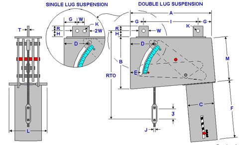
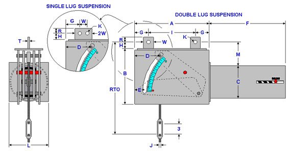
Figure PTP 100-B is a vertical constant suspended from a beam. It can be furnished with single lug suspension or double lug suspension as shown above.
ORDERING: Specify figure number, size, type, load, actual travel, total travel and direction of travel. For load and travel not in the tables, please call for dimensions.
Important Notes: ALL DIMENSIONS ARE IN INCHES UNLESS OTHERWISE NOTED.
• RTO – Rod take out for down travel
• D – J-Rod position for down travel
• E – J-Rod position for up travel
• F – Maximum length for the load range
• WT – Maximum weight for the load rang
J-Rod and Lug Selection
LOAD
(lbs)
0
765
766
1491
1492
2402
2403
3868
3869
5663
5664
9121
9122
13354
13355
17775
17776
23659
23660
28627
28628
38103
38104
46104
46105
60000
J-ROD
1/2
5/8
5/4
1
1 1/4
1 1/2
1 3/4
2
2 1/4
2 1/2
2 3/4
3
3 1/4
K-HOLE
11/16
13/16
15/16
1 1/4
1 1/2
1 3/4
2
2 3/8
2 5/8
2 7/8
3 1/8
3 3/8
3 5/8
H
1 1/2
1 1/2
1 1/2
2
3
3
3
4
4 1/2
4 1/2
4 1/2
5
5
R
1 1/4
1 1/4
1 1/4
1 1/2
2
2 1/2
2 1/2
3
3
4
4
4
4 1/2
T
1/4
1/4
1/8
1/2
5/8
3/4
3/4
3/4
3/4
1
1
1
1
W
2 1/2
2 1/2
2 1/2
3
4
5
5
6
6
8
8
8
9
Total Travel 1 1/2 to 4 Inches
LOAD
RANGE (lbs)
J-ROD
RTO*
A
B
C
D
E
F
G
I
L
M
WT (lbs)
44 -243
1/2
15 9/16
16 3/8
9 11/16
6 5/8
3 3/4
2
12
1 7/8
12 5/8
7 5/8
8
65
244 -
1018
1/2
15 9/16
17 3/8
10 1/8
8 5/8
3 3/4
2
15
2 3/8
12 5/8
11 5/8
8 3/8
105
5/8
15 9/16
1019 -
3516
5/8
15 3/4
17 3/8
11 1/8
8 5/8
3 3/4
2
22
2 3/8
12 5/8
11 5/8
9 1/4
225
3/4
15 3/4
1
18 1/4
3517 -
7538
1
18 13/16
20 3/8
12 1/2
8 5/8
4 5/16
2 9/16
33
3 1/2
13 3/8
11 5/8
10 1/8
395
1 1/4
20 13/16
1 1/2
21 1/16
7539 –
16159
1 1/2
22 1/16
23 9/16
15 3/8
12 3/4
5 9/16
3 7/8
44
4 3/8
14 13/16
18 3/8
12 5/8
1045
1 3/4
23 9/16
2
28 9/16
16160 -
31490
2
30 3/4
24 1/4
18 15/16
12 3/4
6 3/4
5
58
6 1/2
11 1/4
18 3/8
16 1/16
1700
2 1/4
33 1/4
2 1/2
33 1/4
2 3/4
35 1/4
*Rod Take Out (RTO) is for down travel [ Add 4 inches for up travel ]
Total Travel 4 1/2 to 6 Inches
LOAD
RANGE (lbs)
J-ROD
RTO*
A
B
C
D
E
F
G
I
L
M
WT (lbs)
34 -183
1/2
15 9/16
18 11/16
12
6 5/8
4 1/2
1 7/8
12
2
14 11/16
7 5/8
10 1/16
75
184 -765
1/2
15 9/16
19 11/16
12 1/2
8 5/8
4 1/2
1 7/8
15
2 3/4
14 3/16
11 5/8
10 1/2
115
766 -
2402
5/8
15 3/4
19 11/16
13 5/8
8 5/8
4 1/2
1 7/8
22
2
15 11/16
11 5/8
11 1/2
230
3/4
15 3/4
2403
5663
1
18 13/16
22 13/16
15
8 5/8
5 1/4
2 5/8
33
3 1/4
16 5/16
11 5/8
12 7/16
400
1 1/4
20 13/16
5664 -
1 1/2
21 5/8
25 1/4
17 5/16
12 3/4
5 3/4
3 1/8
44
3 3/4
17 3/4
18 3/8
14 7/16
1035
12140
1 3/4
23 1/8
12141 -
23659
1 3/4
25 5/16
26 5/8
20 7/8
12 3/4
7 1/4
4 5/8
58
6 5/8
13 3/8
18 3/8
17 7/8
1640
2
30 5/16
2 1/4
32 13/16
*Rod Take Out (RTO) is for down travel [ Add 6 inches for up travel ]
Total Travel 6 1/2 to 8 Inches
LOAD RANGE (lbs)
J-ROD
RTO*
A
B
C
D
E
F
G
I
L
M
WT (lbs)
25 - 151
1/2
19 15/16
21 1/4
14 1/2
6 5/8
5 9/16
2
12
2 1/4
16 3/4
7 5/8
12 5/16
90
152 - 632
1/2
19 9 /16
22 1/4
15
8 5/8
5 9/16
2
15
2 1/4
17 3/4
11 5/8
12 3/4
130
633 - 1985
1/2
19 3/4
22 1/4
16
8 5/8
5 9/16
2
22
2 1/4
17 3/4
11 5/8
13 5/8
255
5/8
19 3/4
5/4
19 3/4
1986 - 4680
3/4
20 5 /16
25 1/8
16 7/8
8 5/8
6 1/16
2 1/2
33
3
19 1/8
11 5/8
14 1/8
420
1
22 13/16
1 1/4
24 13 /16
4681 - 10033
1 1/4
25 3/8
27 13/16
19 15/16
12 3/4
6 13/16
3 1/4
44
3 1/2
20 13/16
18 3/8
16 13/16
1090
1 1/2
25 5/8
1 3/4
27 1/8
10034 - 19552
1 3/4
28 7/8
30 3/16
23 7/16
12 3/4
9 5/16
5 3/4
58
4 3/4
20 13/16
18 3/8
20 1/8
1700
2
33 7/8
2 1/4
36 3/8
*Rod Take Out (RTO) is for down travel [ Add 8 inches for up travel ]
Total Travel 8 1/2 to 10 Inches
LOAD RANGE (lbs)
J-ROD
RTO*
A
B
C
D
E
F
G
I
L
M
WT (lbs)
21 - 125
1/2
21 9 /16
23 3/4
16 5/8
6 5/8
6 5/8
2 1/8
12
2 3/4
18 1/4
7 5/8
14 1/4
100
126 - 522
1/2
21 9 /16
24 13/16
16 7/8
8 5/8
6 5/8
2 1/8
15
2 3/4
19 5/16
11 5/8
14 3/8
145
523 - 1640
1/2
21 3/4
24 3/4
18
8 5/8
6 5/8
2 1/8
22
2 3/4
19 1/4
11 5/8
15 3/4
280
5/8
21 3 /4
3/4
21 3/4
1641 - 3868
3/4
21 7/8
27 1/4
18 3/4
8 5/8
6 7/8
2 3/8
33
3 1/2
20 1/4
11 5/8
15 3/4
430
1
24 3/8
3869 - 8292
11/4
26 7/8
29 7/8
21 3/4
12 3/4
7 3/8
2 7/8
44
3 1/2
22 7/8
18 3/8
18 3/8
1115
1 1/2
27 3/16
8293 - 16159
1 1/2
28 1/16
31 1/16
23 15/16
12 3/4
8 5/8
4 1/8
58
5 1/4
20 9/16
18 3/8
20 1/2
1685
1 3/4
29 9/16
2
34 9/16
*Rod Take Out (RTO) is for down travel [ Add 10 inches for up travel ]
Total Travel 10 1/2 to 12 Inches
LOAD RANGE (lbs)
J-ROD
RTO*
A
B
C
D
E
F
G
I
L
M
WT (lbs)
17 - 103
1/2
23 9/16
26 3/8
19
6 5/8
7 5/8
2 1/4
12
3 1/4
19 7/8
7 5/8
16 3/8
120
104 - 432
1/2
23 1/2
27 3/8
19 1/2
8 5/8
7 5/8
2 1/4
15
3 1/4
20 7/8
11 5/8
16 3/4
160
433 - 1491
1/2
23 11/16
27 3/8
20 1/8
8 5/8
7 5/8
2 1/4
22
3 1/8
21 1/8
11 5/8
17 5/16
300
5/6
23 11/16
1492 - 3197
3/4
23 7/8
29 3/4
21
8 5/8
7 5/8
2 1/4
33
3 3/8
23
11 5/8
7 13/16
475
1
26 3/8
3198 - 6853
1
26 15/16
32 1/2
23 7/8
12 3/4
8 3/8
3
44
3 5/8
25 1/4
18 3/8
20 5/16
1170
1 1/4
28 15/16
1 1/2
29 3/16
6854 - 13354
1 1/2
30 1 /16
33 5/8
26 1/8
12 3/4
9 5/8
4 1/4
58
3 1/4
29 1/8
18 3/8
22 1/2
1710
1 3/4
31 9 /16
*Rod Take Out (RTO) is for down travel [ Add 12 inches for up travel ]
Total Travel 12 1/2 to 14 Inches
LOAD RANGE (lbs)
J-ROD
RTO*
A
B
C
D
E
F
G
I
L
M
WT (lbs)
17 - 94
1/2
25 9/16
28 5/8
20 15/16
6 5/8
8 1/2
2 1/8
12
3 3/4
21 1/8
7 5/8
18 1/8
135
95 - 392
1/2
25 9/16
29 11/16
21 1/2
8 5/8
8 1/2
2 1/8
15
3 3/4
22 3/16
11 5/8
18 5/8
180
393 - 1232
1/2
25 11/16
29 11/16
22 11/16
8 5/8
8 1/2
2 1/8
22
3 3/4
22 3/16
11 5/8
19 5/8
330
5/8
25 11/16
1233 - 2906
5/8
25 7/8
32 5/16
23
8 5/8
8 3/4
2 3/8
33
3 3/4
24 13/16
11 5/8
19 5/8
510
3/4
25 7/8
1
28 3/8
2907 - 6230
1
28 15/16
34 3/4
26 1/16
12 3/4
9 1/4
2 7/8
44
4 1/4
26 1/4
18 3/8
22 5/16
1225
1 1/4
30 15/16
1 1/2
31 3/16
6231 - 12140
1 1/2
31 5/8
35 1/2
27 13/16
12 3/4
10
3 5/8
58
3 3/4
28
18 3/8
24
1755
1 3/4
33 1/8
*Rod Take Out (RTO) is for down travel [ Add 14 inches for up travel ]
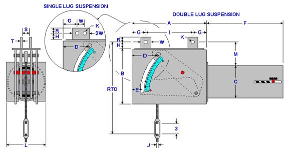
Figure PTP 100-C is a vertical constant suspended from a beam. It can be furnished with single lug suspension or double lug suspension as shown above.
ORDERING: Specify figure number, size, type, load, actual travel, total travel and direction of travel. For load and travel not in the tables, please call for dimensions.
Important Notes: ALL DIMENSIONS ARE IN INCHES UNLESS OTHERWISE NOTED.
• RTO – Rod take out for down travel
• D – J-Rod position for down travel
• E – J-Rod position for up travel
• F – Maximum length for the load range
• WT – Maximum weight for the load range
J-Rod and Lug Selection
LOAD
(lbs)
0
765
766
1491
1492
2402
2403
3868
3869
5663
5664
9121
9122
13354
13355
17775
17776
23659
23660
28627
28628
38103
38104
46104
46105
60000
J-ROD
1/2
5/8
3/4
1
1 1/4
1 1/2
1 3/4
2
2 1/4
2 1/2
2 3/4
3
3 1/4
K-HOLE
11/16
13/16
15/16
1 1/4
1 1/2
1 3/4
2
2 3/8
2 5/8
2 7/8
3 1/8
3 3/8
3 5/8
H
1 1/2
1 1/2
1 1/2
2
3
3
3
4
4 1/2
4 1/2
4 1/2
5
5
R
1 1/4
1 1/4
1 1/4
1 1/2
2
2 1/2
2 1/2
3
3
4
4
4
4 1/2
S
7/8
1 1/16
1 1/4
1 5/8
2
2 3/8
2 5/8
2 7/8
3 1/8
3 3/8
3 5/8
3 7/8
4 1/8
T
1/4
1/4
3/8
1/2
5/8
3/4
3/4
3/4
3/4
1
1
1
1
W
2 1/2
2 1/2
2 1/2
3
4
5
5
6
6
8
8
8
9
Total Travel 1 1/2 to 4 Inches
LOAD
RANGE (lbs)
J-ROD
RTO*
A
B
C
D
E
F
G
I
L
M
WT (lbs)
44 -243
1/2
15 9/16
16 3/8
9 11/16
6 5/8
3 3/4
2
12
1 7/8
12 5/8
7 5/8
8
65
244 –
1018
1/2
15 9/16
17 3/8
10 1/8
8 5/8
3 3/4
2
15
2 3/8
12 5/8
11 5/8
8 3/8
105
5/8
15 9/16
1019 –
3516
5/8
15 3/4
17 3/8
11 1/8
8 5/8
3 3/4
2
22
2 3/8
12 5/8
11 5/8
9 1/4
225
3/4
15 3/4
1
18 1/4
3517 –
7538
1
18 13/16
20 3/8
12 1/2
8 5/8
4 5/16
2 9/16
33
3 1/2
13 3/8
11 5/8
10 1/8
395
1 1/4
20 13/16
1 1/2
21 1/16
7539 –
16159
1 1/2
22 1/16
23 9/16
15 3/8
12 3/4
5 9/16
3 7/8
44
4 3/8
14 13/16
18 3/8
12 5/8
1,045
1 3/4
23 9/16
2
28 9/16
16160 –
31490
2
30 3/4
24 1/4
18 15/16
12 3/4
6 3/4
5
58
6 1/2
11 1/4
18 3/8
16 1/16
1,700
2 1/4
33 1/4
2 1/2
33 1/4
23/4
35 1/4
*Rod Take Out (RTO) is for down travel [ Add 4 inches for up travel ]
Total Travel 4 1/2 to 6 Inches
LOAD
RANGE (lbs)
J-ROD
RTO*
A
B
C
D
E
F
G
I
L
M
WT (lbs)
34 -183
1/2
15 9/16
18 11/16
12
6 5/8
4 1/2
1 7/8
12
2
14 11/16
7 5/8
10 1/16
75
184 -765
1/2
15 9/16
19 11/16
12 1/2
8 5/8
4 1/2
1 7/8
15
2 3/4
14 3/16
11 5/8
10 1/2
115
766 –
2402
5/8
15 3/4
19 11/16
13 5/8
8 5/8
4 1/2
1 7/8
22
2
15 11/16
11 5/8
11 1/2
230
3/4
15 3/4
2403 –
5663
1
18 13/16
22 13/16
15
8 5/8
5 1/4
2 5/8
33
3 1/4
16 5/16
11 5/8
12 7/16
400
1 1/4
20 13/16
5664 –
12140
1 1/2
21 5/8
25 1/4
17 5/16
12 3/4
5 3/4
3 1/8
44
3 3/4
17 3/4
18 3/8
14 7/16
1,035
1 3/4
23 1/8
12141 –
23659
1 3/4
25 5/16
26 5/8
20 7/8
12 3/4
7 1/4
4 5/8
58
6 5/8
13 3/8
18 3/8
17 7/8
1,640
2
30 5/16
2 1/4
32 13/16
*Rod Take Out (RTO) is for down travel [ Add 6 inches for up travel ]
Total Travel 6 1/2 to 8 Inches
LOAD RANGE (lbs)
J-ROD
RTO*
A
B
C
D
E
F
G
I
L
M
WT (lbs)
25 – 151
1/2
19 9/16
21 1/4
14 1/2
6 5/8
5 9/16
2
12
2 1/4
16 3/4
7 5/8
12 5/16
90
152 – 632
1/2
19 9/16
22 1/4
15
8 5/8
5 9/16
2
15
2 1/4
17 3/4
11 5/8
12 3/4
130
633 – 1985
1/2
19 3/4
22 1/4
16
8 5/8
5 9/16
2
22
2 1/4
17 3/4
11 5/8
13 5/8
255
5/8
19 3/4
3/4
19 3/4
1986 – 4680
3/4
20 5 /16
25 1/8
16 7/8
8 5/8
6 1/16
2 1/2
33
3
19 1/8
11 5/8
14 1/8
420
1
22 13/16
1 1/4
24 13/16
4681 – 10033
1 1/4
25 3/8
27 13/16
19 15/16
12 3/4
6 13/16
3 1/4
44
3 1/2
20 13/16
18 3/8
16 13/16
1,090
1 1/2
25 5/8
1 3/4
27 1/8
10034 – 19552
1 3/4
28 7/8
30 3/16
23 7/16
12 3/4
9 5/16
5 3/4
58
4 3/4
20 11/16
18 3/8
20 1/8
1,700
2
33 7/8
2 1/4
36 3/8
*Rod Take Out (RTO) is for down travel [ Add 8 inches for up travel ]
Total Travel 8 1/2 to 10 Inches
LOAD RANGE (lbs)
J-ROD
RTO*
A
B
C
D
E
F
G
I
L
M
WT (lbs)
21 – 125
1/2
21 9 /16
23 3/4
16 5/8
6 5/8
6 5/8
2 1/8
12
2 3/4
18 1/4
7 5/8
14 1/4
100
126 – 522
1/2
21 9 /16
24 13/16
16 7/8
8 5/8
6 5/8
2 1/8
15
2 3/4
19 5/16
11 5/8
14 3/8
145
523 – 1640
1/2
21 3/4
24 3/4
18
8 5/8
6 5/8
2 1/8
22
2 3/4
19 1/4
11 5/8
15 3/8
280
5/8
21 3 /4
3/4
21 3/4
1641 – 3868
3/4
21 7/8
27 1/4
18 3/4
8 5/8
6 7/8
2 3/8
33
3 1/2
20 1/4
11 5/8
15 3/4
430
1
24 3/8
3869 – 8292
11/4
26 15/16
29 7/8
21 3/4
12 3/4
7 3/8
2 7/8
44
3 1/2
22 7/8
18 3/8
18 3/8
1,115
1 1/2
27 3/16
8293 – 16159
1 1/2
28 1/16
31 1/16
23 15/16
12 3/4
8 5/8
4 1/8
58
5 1/4
20 9/16
18 3/8
20 1/2
1,685
1 3/4
29 9/16
2
34 9/16
*Rod Take Out (RTO) is for down travel [ Add 10 inches for up travel ]
Total Travel 10 1/2 to 12 Inches
LOAD RANGE (lbs)
J-ROD
RTO*
A
B
C
D
E
F
G
I
L
M
WT (lbs)
17 – 103
1/2
23 9/16
26 3/8
19
6 5/8
7 5/8
2 1/4
12
3 1/4
19 7/8
7 5/8
16 3/8
120
104 – 432
1/2
23 1/2
27 3/8
19 1/2
8 5/8
7 5/8
2 1/4
15
3 1/4
20 7/8
11 5/8
16 3/4
160
433 – 1491
1/2
23 11/16
27 3/8
20 1/8
8 5/8
7 5/8
2 1/4
22
3 1/8
21 1/8
11 5/8
17 5/16
300
5/8
23 11/16
1492 – 3197
3/4
23 7/8
29 3/4
21
8 5/8
7 5/8
2 1/4
33
3 3/8
23
11 5/8
17 13/16
475
1
26 3/8
3198 – 6853
1
26 15/16
32 1/2
23 7/8
12 3/4
8 3/8
3
44
3 5/8
25 1/4
18 3/8
20 5/16
1,170
1 1/4
28 15/16
1 1/2
29 3/16
6854 – 13354
1 1/2
30 1/16
33 5/8
26 1/8
12 3/4
9 5/8
4 1/4
58
3 1/4
29 1/8
18 3/8
22 1/2
1,710
1 3/4
31 9/16
*Rod Take Out (RTO) is for down travel [ Add 12 inches for up travel ]
Total Travel 12 1/2 to 14 Inches
LOAD RANGE (lbs)
J-ROD
RTO*
A
B
C
D
E
F
G
I
L
M
WT (lbs)
17 – 94
1/2
25 9/16
28 5/8
20 15/16
6 5/8
8 1/2
2 1/8
12
3 3/4
21 1/8
7 5/8
18 1/8
135
95 – 392
1/2
25 9/16
29 11/16
21 1/2
8 5/8
8 1/2
2 1/8
15
3 3/4
22 3/16
11 5/8
18 5/8
180
393 – 1232
1/2
25 11/16
29 11/16
22 11/16
8 5/8
8 1/2
2 1/8
22
3 3/4
22 3/16
11 5/8
19 5/8
330
5/8
25 11/16
1233 – 2906
5/8
25 7/8
32 5/16
23
8 5/8
8 3/4
2 3/8
33
3 3/4
24 13/16
11 5/8
19 9/16
510
3/4
25 7/8
1
28 3/8
2907 – 6230
1
28 15/16
34 3/4
26 1/16
12 3/4
9 1/4
2 7/8
44
4 1/4
26 1/4
18 3/8
22 5/16
1,225
1 1/4
30 15/16
1 1/2
31 3/16
6231 – 12140
1 1/2
31 5/8
35 1/2
27 13/16
12 3/4
10
3 5/8
58
3 3/4
28
18 3/8
24
1,755
1 3/4
33 1/8
*Rod Take Out (RTO) is for down travel [ Add 14 inches for up travel ]
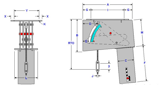
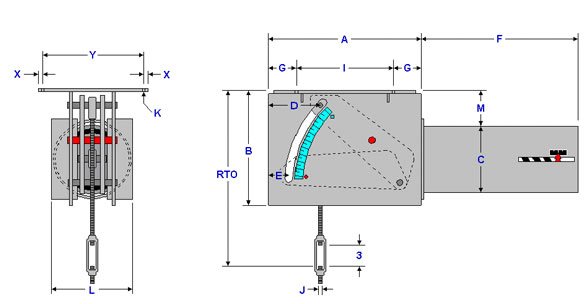
Figure PTP 100-D is a vertical constant with a top attachment which is bolted directly to the bottom of the steel as shown above.
ORDERING: Specify figure number, size, type, load, actual travel, total travel and direction of travel. For load and travel not in the tables, please call for dimensions.
Important Notes: ALL DIMENSIONS ARE IN INCHES UNLESS OTHERWISE NOTED.
• RTO – Rod take out for down travel
• D – J-Rod position for down travel
• E – J-Rod position for up travel
• F – Maximum length for the load range
• WT – Maximum weight for the load range
J-Rod and Top Attachment Selection
LOAD
(lbs)
0
765
766
1491
1492
2402
2403
3868
3869
5663
5664
9121
9122
13354
13355
17775
17776
23659
23660
28627
28628
38103
38104
46104
46105
60000
J-ROD
1/2
5/8
3/4
1
1 1/4
1 1/2
1 3/4
2
2 1/4
2 1/2
2 3/4
3
3 1/4
K-HOLE
9/16
3/4
3/4
3/4
3/4
7/8
7/8
1 3/8
1 3/8
1 5/8
1 5/8
1 5/8
1 5/8
X
3/4
7/8
7/8
1 1/8
1 1/8
1 3/8
1 3/8
1 5/8
1 5/8
2
2
2
2
Y
5 5/8
8
8
10 3/4
10 3/4
12 5/8
12 5/8
14 5/8
14 5/8
15
15
15
15
Total Travel 1 1/2 to 4 Inches
LOAD
RANGE (lbs)
J-ROD
RTO*
A
B
C
D
E
F
G
I
L
M
WT (lbs)
44 -243
1/2
14 1/16
16 3/8
9 11/16
6 5/8
3 3/4
2
12
1 7/8
12 5/8
7 5/8
8
65
244 –
1018
1/2
14 1/16
17 3/8
10 1/8
8 5/8
3 3/4
2
15
2 3/8
12 5/8
11 5/8
8 3/8
105
5/8
14 1/16
1019 –
3516
5/8
14 1/4
17 3/8
11 1/8
8 5/8
3 3/4
2
22
2 3/8
12 5/8
11 5/8
9 1/4
225
3/4
14 1/4
1
16 1/4
3517 –
7538
1
16 13/16
20 3/8
12 1/2
8 5/8
4 5/16
2 9/16
33
3 1/2
13 3/8
11 5/8
10 1/8
395
1 1/4
17 13/16
1 1/2
18 1/16
7539 –
16159
1 1/2
19 1/16
23 9/16
15 3/8
12 3/4
5 9/16
3 7/8
44
4 3/8
14 13/16
18 3/8
12 5/8
1,045
1 3/4
20 9/16
2
24 9/16
16160 –
31490
2
26 3/4
24 1/4
1815/16
12 3/4
6 3/4
5
58
6 1/2
11 1/4
18 3/8
16 1/16
1,700
2 1/4
28 3/4
2 1/2
28 3/4
2 3/4
30 3/4
*Rod Take Out (RTO) is for down travel [ Add 4 inches for up travel ]
Total Travel 4 1/2 to 6 Inches
LOAD
RANGE (lbs)
J-ROD
RTO*
A
B
C
D
E
F
G
I
L
M
WT (lbs)
34 – 183
1/2
14 1/16
18 11/16
12
6 5/8
4 1/2
1 7/8
12
2
14 11/16
7 5/8
10 1/16
75
184 –
765
1/2
14 1/16
19 11/16
12 1/2
8 5/8
4 1/2
1 7/8
15
2 3/4
14 3/16
11 5/8
10 1/2
115
766 –
2402
5/8
14 1/4
19 11/16
13 5/8
8 5/8
4 1/2
1 7/8
22
2
15 11/16
11 5/8
11 1/2
230
3/4
14 1/4
2403 –
5663
1
16 13/16
22 13/16
15
8 5/8
5 1/4
2 5/8
33
3 1/4
16 5/16
11 5/8
12 7/16
400
1 1/4
17 13/16
5664 –
12140
1 1/2
18 5/8
25 1/4
17 5/16
12 3/4
5 3/4
3 1/8
44
3 3/4
17 3/4
18 3/8
14 7/16
1,035
1 3/4
20 1/8
12141 –
23659
1 3/4
22 5/16
26 5/8
20 7/8
12 3/4
7 1/4
4 5/8
58
6 5/8
13 3/8
18 3/8
17 7/8
1,640
2
26 5/16
2 1/4
28 5/16
*Rod Take Out (RTO) is for down travel [ Add 6 inches for up travel ]
Total Travel 6 1/2 to 8 Inches
LOAD RANGE (lbs)
J-ROD
RTO*
A
B
C
D
E
F
G
I
L
M
WT (lbs)
25 – 151
1/2
18 1/16
21 1/4
14 1/2
6 5/8
5 9/16
2
12
2 1/4
16 3/4
7 5/8
12 5/16
90
152 – 632
1/2
18 1/16
22 1/4
15
8 5/8
5 9/16
2
15
2 1/4
17 3/4
11 5/8
12 3/4
130
633 – 1985
1/2
18 1/4
22 1/4
16
8 5/8
5 9/16
2
22
2 1/4
17 3/4
11 5/8
13 5/8
255
5/8
18 1/4
3/4
18 1/4
1986 – 4680
3/4
18 13/16
25 1/8
16 7/8
8 5/8
6 1/16
2 1/2
33
3
19 1/8
11 5/8
14 1/8
420
1
20 13/16
1 1/4
21 13/16
4681 – 10033
1 1/4
22 3/8
27 13/16
19 15/16
12 3/4
6 13/16
3 1/4
44
3 1/2
20 13/16
18 3/8
16 13/16
1,090
1 1/2
22 5/8
1 3/4
24 1/8
10034 – 19552
1 3/4
25 7/8
30 3/16
23 7/16
12 3/4
9 5/16
5 3/4
58
4 3/4
20 11/16
18 3/8
20 1/8
1,700
2
29 7/8
2 1/4
31 7/8
*Rod Take Out (RTO) is for down travel [ Add 8 inches for up travel ]
Total Travel 8 1/2 to 10 Inches
LOAD RANGE (lbs)
J-ROD
RTO*
A
B
C
D
E
F
G
I
L
M
WT (lbs)
21 – 125
1/2
20 1/16
23 3/4
16 5/8
6 5/8
6 5/8
2 1/8
12
2 3/4
18 1/4
7 5/8
14 1/4
100
126 – 522
1/2
20 1/16
24 13/16
16 7/8
8 5/8
6 5/8
2 1/8
15
2 3/4
19 5/16
11 5/8
14 3/8
145
523 – 1640
1/2
20 1/4
24 3/4
18
8 5/8
6 5/8
2 1/8
22
2 3/4
19 1/4
11 5/8
15 3/8
280
5/8
20 1/4
3/4
20 1/4
1641 – 3868
3/4
20 3/8
27 1/4
18 3/4
8 5/8
6 7/8
2 3/8
33
3 1/2
20 1/4
11 5/8
15 3/4
430
1
22 3/8
3869 – 8292
11/4
23 15/16
29 7/8
21 3/4
12 3/4
7 3/8
2 7/8
44
3 1/2
22 7/8
18 3/8
18 3/8
1,115
1 1/2
24 3/16
8293 – 16159
1 1/2
25 1/16
31 1/16
23 15/16
12 3/4
8 5/8
4 1/8
58
5 1/4
20 9/16
18 3/8
20 1/2
1,685
1 3/4
26 9/16
2
30 9/16
*Rod Take Out (RTO) is for down travel [ Add 10 inches for up travel ]
Total Travel 10 1/2 to 12 Inches
LOAD RANGE (lbs)
J-ROD
RTO*
A
B
C
D
E
F
G
I
L
M
WT (lbs)
17 – 103
1/2
22 1/16
26 3/8
19
6 5/8
7 5/8
2 1/4
12
3 1/4
19 7/8
7 5/8
16 3/8
120
104 – 432
1/2
22
27 3/8
19 1/2
8 5/8
7 5/8
2 1/4
15
3 1/4
20 7/8
11 5/8
16 3/4
160
433 – 1491
1/2
22 3/16
27 3/8
20 1/8
8 5/8
7 5/8
2 1/4
22
3 1/8
21 1/8
11 5/8
17 5/16
300
5/8
22 3/16
1492 – 3197
3/4
22 3/8
29 3/4
21
8 5/8
7 5/8
2 1/4
33
3 3/8
23
11 5/8
17 13/16
475
1
24 3/8
3198 – 6853
1
24 15/16
32 1/2
23 7/8
12 3/4
8 3/8
3
44
3 5/8
25 1/4
18 3/8
20 5/16
1,170
1 1/4
25 15/16
1 1/2
26 3/16
6854 – 13354
1 1/2
27 1/16
33 5/8
26 1/8
12 3/4
9 5/8
4 1/4
58
3 1/4
29 1/8
18 3/8
22 1/2
1,710
1 3/4
28 9/16
*Rod Take Out (RTO) is for down travel [ Add 12 inches for up travel ]
Total Travel 12 1/2 to 14 Inches
LOAD RANGE (lbs)
J-ROD
RTO*
A
B
C
D
E
F
G
I
L
M
WT (lbs)
17 – 94
1/2
24 1/16
28 5/8
20 15/16
6 5/8
8 1/2
2 1/8
12
3 3/4
21 1/8
7 5/8
18 1/8
135
95 – 392
1/2
24 1/16
29 11/16
21 1/2
8 5/8
8 1/2
2 1/8
15
3 3/4
22 3/16
11 5/8
18 5/8
180
393 – 1232
1/2
24 3/16
29 11/16
22 11/16
8 5/8
8 1/2
2 1/8
22
3 3/4
22 3/16
11 5/8
19 5/8
330
5/8
24 3/16
1233 – 2906
5/8
24 3/8
32 5/16
23
8 5/8
8 3/4
2 3/8
33
3 3/4
24 13/16
11 5/8
19 9/16
510
3/4
24 3/8
1
26 3/8
2907 – 6230
1
26 15/16
34 3/4
26 1/16
12 3/4
9 1/4
2 7/8
44
4 1/4
26 1/4
18 3/8
22 5/16
1,225
1 1/4
27 15/16
1 1/2
28 3/16
6231 – 12140
1 1/2
28 5/8
35 1/2
27 13/16
12 3/4
10
3 5/8
58
3 3/4
28
18 3/8
24
1,755
1 3/4
30 1/8
*Rod Take Out (RTO) is for down travel [ Add 14 inches for up travel ]
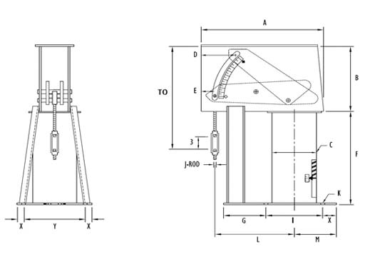
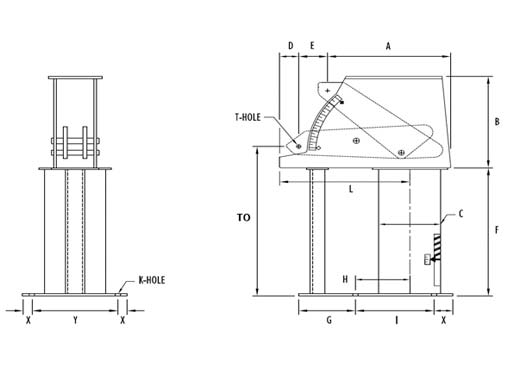
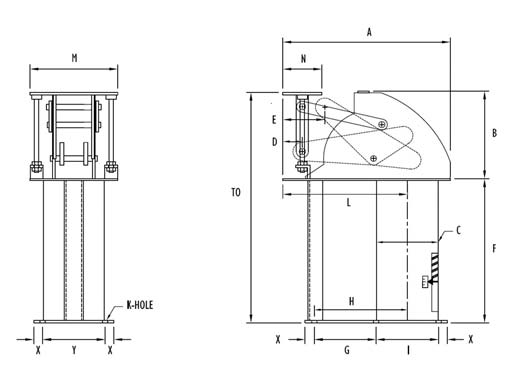
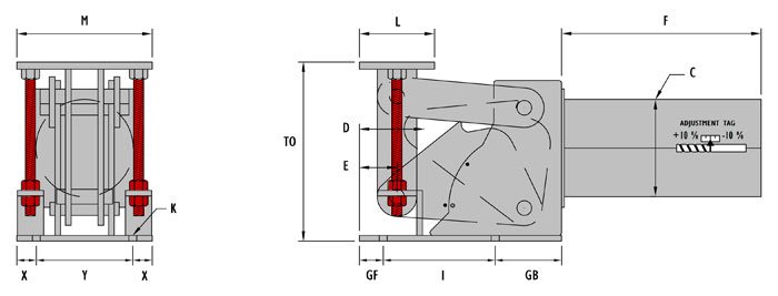
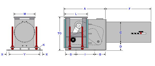
PTP figure 100 type E (Layout-A) is a vertical constant with a base plate which is bolted directly to the top of the steel. The rod take out (RTO) given in the tables below are maximum and made to not reach the supporting steel. The rod take out (RTO) can be specified to exceed the maximum. For load and travel not in the tables, please call for dimensions.
ORDERING: Specify figure number, layout, size, type, description, load, actual travel, total travel and direction of travel. For load and travel not in the tables, please call for dimensions.
Important Notes: ALL DIMENSIONS ARE IN INCHES UNLESS OTHERWISE NOTED.
• TO – Take out for up travel
• D – J-Rod position for down travel
• E – J-Rod position for up travel
• L – Maximum length for the load range
• WT – Maximum weight for the load range
J-Rod Selection
LOAD (lb.)
0 – 765
766 – 1491
1492 – 2402
2403 – 3868
3869 – 5663
5664 – 9121
9122 – 13354
13355 – 17775
17776 – 23659
23660 – 28627
28628 – 38103
38104 – 46104
46105 – 60000
J-ROD
1/2
5/8
3/4
1
1 1/4
1 1/2
1 3/4
2
2 1/4
2 1/2
2 3/4
3
3 1/4
K-HOLE
9/16
3/4
3/4
3/4
3/4
7/8
7/8
1 3/8
1 3/8
1 5/8
1 5/8
1 5/8
1 5/8
Total Travel 1-1/2 to 4 inches
LOAD RANGE (lb.)
J-ROD
RTO*
A
B
C
D
E
G
I
L
M
X
Y
WT (lb.)
44-243
1/2
17 3/4
17
8
6 5/8
3 3/4
2
4
8
10 5/8
4 1/4
1
6 1/2
85
244-1018
1/2
17 3/4
18
8 1/4
8 5/8
3 3/4
2
4 1/2
9 1/2
10 3/4
5 1/4
1
8
125
5/8
17 3/4
1019-3516
5/8
17 7/8
18 1/8
9 1/8
8 5/8
3 3/4
2
5
9 1/2
10 3/4
5 3/4
1 1/2
8
245
3/4
17 7/8
1
19 7/8
3517-7538
1
20 1/4
21 1/4
10 1/8
8 5/8
4 5/16
2 9/16
6 1/4
10
13 1/8
6 1/4
1 1/2
9
395
1 1/4
21 1/4
1 1/2
21 1/2
7539-16159
1 1/2
22 1/2
24 5/8
12 1/2
12 3/4
5 9/16
3 7/8
7 1/4
15
13 1/8
8 7/8
1 1/2
15
1090
1 3/4
25
2
30
16160-31490
2
32 1/8
26
16
12 3/4
6 3/4
5
9
15
13 1/8
9 3/8
1 3/4
17 1/2
1700
2 1/4
32 1/8
2 1/2
33 1/8
2 3/4
33 1/8
LOAD RANGE (lb.)
44-243
244-357
358-475
476-632
633-841
842-1018
1019-1985
1986-2642
2643-3516
3517-4255
4256-5663
5664-7538
7539-11037
11038-14690
14691-16159
16160-19552
19553-26024
26025-31490
F
13 1/2
14 3/4
15 3/4
13 3/4
14 3/4
16 3/4
19
21
23
25 1/4
28 1/4
32 1/4
33 1/2
37 1/2
42 1/2
44 1/2
47 1/2
58 1/2
“Rod Take Out (RTO) is for up travel [subtract 4 inches for down travel ]
Total Travel 4-1/2 to 6 inches
LOAD RANGE (lb.)
J-ROD
RTO*
A
B
C
D
E
G
I
L
M
X
Y
WT (lb.)
34-183
1/2
19 3/4
19 1/2
10
6 5/8
4 1/2
1 7/8
5
8
13 3/8
4 1/4
1
6 1/2
95
184-765
1/2
19 3/4
20 1/2
10 1/2
8 5/8
4 1/2
1 7/8
5 3/4
9 1/2
13 3/8
5 1/4
1
8
135
766-2402
5/8
19 7/8
20 5/8
11 1/2
8 5/8
4 1/2
1 7/8
6
9 1/2
13 3/8
5 3/4
1 1/2
8
260
3/4
19 7/8
2403-5663
1
22 1/4
23 7/8
12 3/8
8 5/8
5 1/4
2 5/8
7 1/2
10
15 3/4
6 1/4
1 1/2
9
420
1 1/4
23 1/4
5664-12140
1 1/2
24
26 1/2
14 3/8
12 3/4
5 3/4
3 1/8
6 3/4
14
15 3/4
8 1/8
1 1/2
13 1/2
1095
1 3/4
26 1/2
12141-23659
1 3/4
28 5/8
28 1/8
17 3/4
12 3/4
7 1/4
4 5/8
9
15
15 3/4
9 3/8
1 3/4
17 1/2
1715
2
33 5/8
2 1/4
34 5/8
LOAD RANGE (lb.)
34-183
184-268
269-357
358-475
476-632
633-765
766-1491
1492-1985
1986-2402
2403-3197
3198-4680
4681-5663
5664-8292
8293-11037
11038-12140
12141-14690
14691-19552
19553-23659
F
13 1/2
14 3/4
15 3/4
13 3/4
14 3/4
16 3/4
19
21
23
25 1/4
28 1/4
32 1/4
33 1/2
37 1/2
42 1/2
44 1/2
47 1/2
58 1/2
“Rod Take Out (RTO) is for up travel [subtract 6 inches for down travel ]
Total Travel 6-1/2 to 8 inches
LOAD RANGE (lb.)
J-ROD
RTO*
A
B
C
D
E
G
I
L
M
X
Y
WT (lb.)
27-151
1/2
21 3/4
22 1/4
12 1/4
6 5/8
5 9/16
2
6 3/4
8
15 7/8
4 1/4
1
6 1/2
110
152-632
1/2
21 3/4
23 1/4
12 3/4
8 5/8
5 9/16
2
7
9 1/2
15 7/8
5 1/4
1
8
150
633-1985
1/2
25 7/8
23 3/8
13 5/8
8 5/8
5 9/16
2
7 1/2
9 1/2
15 7/8
5 3/4
1 1/2
8
285
5/8
25 7/8
3/4
25 7/8
1986-4680
3/4
26 1/4
26 1/4
14
8 5/8
6 1/16
2 1/2
8 1/8
10
18 3/8
6 1/4
1 1/2
9
445
1
28 1/4
1 1/4
29 1/4
4681-10033
1 1/4
29 3/4
29 1/4
16 3/4
12 3/4
6 13/16
3 1/4
8 1/2
14
18 3/8
8 1/8
1 1/2
13 1/2
1150
1 1/2
30
1 3/4
31 1/2
10034-19552
1 3/4
33 1/4
31 7/8
20
12 3/4
9 5/16
5 3/4
9
14 1/2
18 3/8
8 7/8
1 3/4
17 1/2
1770
2
37 1/4
2 1/4
37 1/4
LOAD RANGE (lb.)
27-151
152-221
222-295
296-392
393-475
476-632
633-1120
1121-1640
1641-1985
1986-2642
2643-3516
3517-4680
4681-6230
6231-8292
8293-10033
10034-11037
11038-14690
14691-19552
F
14 1/2
14 3/4
15 3/4
13 3/4
14 3/4
16 3/4
19
21
23
25 1/4
28 1/4
32 1/4
33 1/2
37 1/2
42 1/2
44 1/2
47 1/2
58 1/2
“Rod Take Out (RTO) is for up travel [subtract 8 inches for down travel ]
Total Travel 8-1/2 to 10 inches
LOAD RANGE (lb.)
J-ROD
RTO*
A
B
C
D
E
G
I
L
M
X
Y
WT (lb.)
22-125
1/2
24 7/8
25
14 1/8
6 5/8
6 5/8
2 1/8
9
8
18 1/2
4 1/4
1
6 1/2
120
126-522
1/2
24 7/8
26
14 3/8
8 5/8
6 5/8
2 1/8
9 1/2
9 1/2
18 1/2
5 1/4
1
8
165
523-1640
1/2
28 7/8
26 1/8
15 3/8
8 5/8
6 5/8
2 1/8
9
9 1/2
18 1/2
5 3/4
1 1/2
8
310
5/8
28 7/8
3/4
28 7/8
1641-3868
3/4
29 7/8
28 5/8
15 3/4
8 5/8
6 7/8
2 3/8
10 3/4
10
20 3/4
6 1/4
1 1/2
9
470
1
31 7/8
3869-8292
1 1/4
33 1/4
31 1/2
18 3/8
12 3/4
7 3/8
2 7/8
9 1/2
14
20 7/8
8 1/8
1 1/2
13 1/2
1180
1 1/2
33 1/2
8293-16159
1 1/2
34 1/2
32 7/8
20 3/8
12 3/4
8 5/8
4 1/8
9 3/4
14 3/4
20 7/8
8 7/8
1 1/2
17 1/2
1790
1 3/4
36
2
40
LOAD RANGE (lb.)
22-125
126-183
184-243
244-324
325-432
433-522
523-1018
1019-1355
1356-1640
1641-2183
2184-2906
2907-3868
3869-5148
5149-6853
6854-8292
8293-9121
9122-12140
12141-16159
F
14 1/2
14 3/4
15 3/4
14 3/4
14 3/4
16 3/4
19
21
23
25 1/4
28 1/4
32 1/4
33 1/2
37 1/2
42 1/2
44 1/2
47 1/2
58 1/2
“Rod Take Out (RTO) is for up travel [subtract 10 inches for down travel ]
Total Travel 10-1/2 to 12 inches
LOAD RANGE (lb.)
J-ROD
RTO*
A
B
C
D
E
G
I
L
M
X
Y
WT (lb.)
20-103
1/2
27 7/8
27 3/4
16 3/8
6 5/8
7 5/8
2 1/4
11
8
21 1/8
4 1/4
1
6 1/2
145
104-432
1/2
30 1/4
28 3/4
16 3/4
8 5/8
7 5/8
2 1/4
10 1/2
9 1/2
21 1/8
5 1/4
1
8
180
433-1491
1/2
30 7/8
28 3/4
17 1/4
8 5/8
7 5/8
2 1/4
11
9 1/2
21 1/8
5 3/4
1 1/2
8
335
5/8
30 7/8
1492-3197
3/4
33 7/8
31 1/4
17 3/4
8 5/8
7 5/8
2 1/4
12 1/2
10
23 1/2
6 1/4
1 1/2
9 1/2
520
1
35 7/8
3198-6853
1
36 3/8
34 1/8
20 1/4
12 3/4
8 3/8
3
11 1/2
14
23 1/2
8 1/8
1 1/2
13 1/2
1240
1 1/4
37 3/8
1 1/2
37 5/8
6854-13354
1 1/2
38 1/2
35 1/2
22 3/8
12 3/4
9 5/8
4 1/4
12 1/4
14 3/4
23 1/2
8 7/8
1 1/2
17 1/2
1825
1 3/4
40
LOAD RANGE (lb.)
20-103
104-151
152-201
202-268
269-357
358-432
433-841
842-1120
1121-1491
1492-1640
1641-2401
2402-3197
3198-4680
4681-6230
6231-6853
6854-8292
8293-11037
11038-13354
F
15 5/8
15 3/4
15 3/4
15 3/4
15 3/4
16 3/4
19
21
23
25 1/4
28 1/4
32 1/4
33 1/2
37 1/2
42 1/2
44 1/2
47 1/2
58 1/2
“Rod Take Out (RTO) is for up travel [subtract 12 inches for down travel ]
Total Travel 12-1/2 to 14 inches
LOAD RANGE (lb.)
J-ROD
RTO*
A
B
C
D
E
G
I
L
M
X
Y
WT (lb.)
19-94
1/2
31 7/8
30 1/4
18
6 5/8
8 1/2
2 1/8
13
8
23 3/4
4 1/4
1
6 1/2
160
95-392
1/2
32 3/8
31 1/4
18 1/2
8 5/8
8 1/2
2 1/8
13
9 1/2
23 3/4
5 1/4
1
8
200
393-1232
1/2
33 7/8
31 3/8
19 1/2
8 5/8
8 1/2
2 1/8
13
9 1/2
23 3/4
5 3/4
1 1/2
8
365
5/8
33 7/8
1233-2906
5/8
35 7/8
34
19 1/2
8 5/8
8 3/4
2 3/8
14 1/2
10
26 1/8
6 1/4
1 1/2
9 1/2
560
3/4
35 7/8
1
37 7/8
2907-6230
1
40 3/8
36 3/8
22 1/4
12 3/4
9 1/4
2 7/8
13 1/2
14
26 1/8
8 1/8
1 1/2
13 1/2
1300
1 1/4
41 3/8
1 1/2
41 5/8
6231-12140
1 1/2
42
37 1/2
24
12 3/4
10
3 5/8
13 3/4
14 3/4
26 1/8
8 7/8
1 1/2
17 1/2
1875
1 3/4
43 1/2
LOAD RANGE (lb.)
19-94
95-137
138-183
184-221
222-295
296-392
393-695
696-1018
1019-1232
1233-1640
1641-2183
2184-2906
2907-3868
3869-5148
5149-6230
6231-6853
6854-9121
9122-12140
F
17 5/8
18 1/4
18 1/4
18 1/4
18 1/4
18 1/4
19
21
23
25 1/4
28 1/4
32 1/4
33 1/2
37 1/2
42 1/2
44 1/2
47 1/2
58 1/2
“Rod Take Out (RTO) is for up travel [subtract 14 inches for down travel ]
PTP 100-E-Constant Spring (Layout-B)
*Drawing shown for down travel
PTP figure 100 type E (Layout-B) is a vertical constant with a base plate which is bolted directly to the top of the steel. The rod take out (RTO) given in the tables below are minimum and may not exceed the depth of the supporting steel. If this is the case, to clear the depth of the supporting steel, the rod take out (RTO) can be specified to exceed the minimum. For load and travel not in the tables, PLEASE CALL FOR DIMENSIONS.
ORDERING: Specify figure number, layout, size, type, description, load, actual travel, total travel and direction of travel. For load and travel not in the tables, please call for dimensions.
Important Notes: ALL DIMENSIONS ARE IN INCHES UNLESS OTHERWISE NOTED.
• TO – Take out for down travel
• D – J-Rod position for down travel
• E – J-Rod position for up travel
• F – Maximum length for the load range
• WT – Maximum weight for the load range
J-Rod Selection
LOAD (lb.)
0 – 392
393 – 765
766 – 1491
1492 – 2402
2403 – 3868
3869 – 5663
5664 – 9121
9122 – 13354
13355 – 17775
17776 – 23659
23660 – 28627
28628 – 38103
38104 – 46104
46105 – 6000
J-ROD
1/2
1/2
5/8
3/4
1
1 1/4
1 1/2
1 3/4
2
2 1/4
2 1/2
2 3/4
3
3 1/4
K-HOLE
9/16
9/16
3/4
3/4
3/4
3/4
7/8
7/8
1 3/8
1 3/8
1 5/8
1 5/8
1 5/8
1 5/8
X
5/8
5/8
5/8
5/8
5/8
5/8
13/16
13/16
1 5/16
1 5/16
1 9/16
1 9/16
1 9/16
1 9/16
Y
5 15/16
8 1/8
8 1/8
8 1/8
10 3/16
10 3/16
12 3/8
12 3/8
14 11/16
14 11/16
14 15/16
14 15/16
14 15/16
14 15/16
Total Travel 1-1/2 to 4 inches
LOAD RANGE (lb.)
J-ROD
TO*
B
C
D
E
F
G
I
L
WT (lb.)
44-243
1/2
7 1/2
10
6 5/8
3 1/4
1 1/2
12
2
7
7 5/8
60
244-1018
1/2
7 1/4
10 1/2
8 5/8
3 1/2
1 3/4
15
1 1/2
8 1/2
11 5/8
100
5/8
7 1/4
1019-3516
5/8
7
11
8 5/8
4
2 1/4
22
2
9
11 5/8
220
3/4
7
1
13
3517-5663
1
12
14
8 5/8
3 3/4
2 1/2
33
2
12
11 5/8
360
1 1/4
12
5664-12140
1 1/2
13 3/8
15
12 3/4
4 3/4
3 15/16
44
2 1/2
14
18 3/8
965
1 3/4
13 3/8
12141-31490
1 3/4
15 1/4
16
12 3/4
5 1/4
4 7/16
61
2 1/2
16
18 3/8
1500
2
15 1/4
2 1/4
15 1/4
2 1/2
15 1/4
2 3/4
15 1/4
“Take Out (TO) is for down travel [add 4 inches for up travel ]
Total Travel 4-1/2 to 6 inches
LOAD RANGE (lb.)
J-ROD
TO*
B
C
D
E
F
G
I
L
WT (lb.)
34-183
1/2
7 1/4
12 1/2
6 5/8
4 3/8
1 3/4
12
2
10
7 7/8
70
184-765
1/2
7 1/8
12 1/2
8 5/8
4 1/2
1 7/8
15
2
10 1/2
11 5/8
110
766-2402
5/8
6 7/8
13 1/2
8 5/8
5 1/8
2 1/2
22
2
12
11 5/8
225
3/4
6 7/8
2403-4680
1
9 3/4
16
8 5/8
5
3
33
2
15
11 5/8
380
1 1/4
9 3/4
4681-10033
1 1/4
12 7/8
17
12 3/4
5
3
44
2 1/2
17
18 3/8
1020
1 1/2
12 7/8
1 3/4
12 7/8
10034-23659
1 3/4
13 7/8
18
12 3/4
5 1/2
3 1/2
61
2 1/2
17
18 3/8
1515
2
13 7/8
2 1/4
13 7/8
“Take Out (TO) is for down travel [add 6 inches for up travel ]
Total Travel 6-1/2 to 8 inches
LOAD RANGE (lb.)
J-ROD
TO*
B
C
D
E
F
G
I
L
WT (lb.)
25-151
1/2
7 1/8
15
6 5/8
5 1/2
1 15/16
12
2 1/2
12
7 5/8
85
152-632
1/2
7
15
8 5/8
5 1/2
1 15/16
15
2 1/2
12
11 5/8
125
633-1985
1/2
6 5/8
16
8 5/8
5 7/8
2 5/16
22
2 1/2
13
11 5/8
245
5/8
6 5/8
3/4
6 5/8
1986-4680
3/4
4 1/2
18
8 5/8
6 3/8
2 13/16
33
2 1/2
14
11 5/8
390
1
5 1/8
1 1/4
14 1/2
4681-10033
1 1/4
14 3/4
19
12 3/4
7
3 7/16
44
2 1/2
19
18 3/8
1050
1 1/2
16 1/4
1 3/4
16 1/4
10034-19552
1 3/4
10 3/4
20
12 3/4
6 1/2
3 11/16
61
2 1/2
19
18 3/8
1535
2
10 3/4
2 1/4
10 3/4
“Take Out (TO) is for down travel [add 8 inches for up travel ]
Total Travel 8-1/2 to 10 inches
LOAD RANGE (lb.)
J-ROD
TO*
B
C
D
E
F
G
I
L
WT (lb.)
21-125
1/2
7 1/8
17
6 5/8
6 1/2
2
12
2 1/2
15
7 5/8
100
126-522
1/2
7
17
8 5/8
6 1/2
2
15
2 12
15
11 5/8
140
523-1640
1/2
6 1/2
18
8 5/8
6 3/4
2 1/4
22
2 1/2
16
11 5/8
270
5/8
6 1/2
3/4
6 1/2
1641-3868
3/4
4 3/4
20
8 5/8
7 1/4
2 3/4
33
2 1/2
17
11 5/8
420
1
10 3/4
3869-8292
1 1/4
10 1/2
21
12 3/4
8
3 1/2
44
3
17
18 3/8
1030
1 1/2
10 3/4
8293-16159
1 1/2
16 1/4
22
12 3/4
9
4 1/2
61
3 1/2
21
18 3/8
1595
1 3/4
16 1/4
2
16 1/4
“Take Out (TO) is for down travel [add 10 inches for up travel ]
Total Travel 10-1/2 to 12 inches
LOAD RANGE (lb.)
J-ROD
TO*
B
C
D
E
F
G
I
L
WT (lb.)
17-103
1/2
5 1/8
19
6 5/8
7
1 5/8
12
2 1/2
17
7 5/8
115
104-432
1/2
5
19
8 5/8
7
1 5/8
15
2 1/2
17
11 5/8
155
433-1491
1/2
4 1/2
20
8 5/8
7 1/2
2 1/8
22
2 1/2
18
11 5/8
290
5/8
4 1/2
1492-3197
3/4
2 1/2
22
8 5/8
8
2 5/8
33
3
18
11 5/8
460
1
8 1/2
3198-6853
1
8 3/4
23
12 3/4
8
2 5/8
44
3
19
18 3/8
1075
1 1/4
8 3/4
1 1/2
8 3/4
6854-13354
1 1/2
11 1/4
24
12 3/4
9
3 5/8
61
3 1/2
20
18 3/8
1575
1 3/4
11 1/4
“Take Out (TO) is for down travel [add 12 inches for up travel ]
Total Travel 12-1/2 to 14 inches
LOAD RANGE (lb.)
J-ROD
TO*
B
C
D
E
F
G
I
L
WT (lb.)
17-94
1/2
5 1/8
21
6 5/8
8
1 11/16
12
3 1/2
18
7 5/8
130
95-392
1/2
5
21
8 5/8
8
1 11/16
15
3 1/2
18
11 5/8
170
393-1232
1/2
4 1/2
22
8 5/8
8 1/2
2 3/16
22
3 1/2
19
11 5/8
320
5/8
4 1/2
1233-2906
5/8
2 5/8
24
8 5/8
9
2 11/16
33
4
19
11 5/8
495
3/4
2 5/8
1
8 5/8
2907-6230
1
8 3/8
25
12 3/4
9
2 11/16
44
4
20
18 3/8
1130
1 1/4
8 3/8
1 1/2
8 3/8
6231-12140
1 1/2
11 1/2
26
12 3/4
10
3 11/16
61
4
21
18 3/8
1620
1 3/4
11 1/2
“Take Out (TO) is for down travel [add 14 inches for up travel ]
Layout -A Shown | For Layout-B, scroll down
*Drawing shown for up travel
PTP figure 100 type F (Layout-A) is a vertical constant designed to support piping from below using a Sway Strut. The base plate is bolted directly to the top of the steel or floor. It is important to understand that this constant has vertical movement subjected by the total travel and an axial movement (E) due to the angle of rotation. If axial movement cannot be tolerated, then a PTP figure 100 type U (vertical upthrust constant) would be appropriate for the application. For load and travel not in the tables, PLEASE CALL FOR DIMENSIONS.
ORDERING: Specify figure number, layout, size, type, description, load, actual travel, total travel and direction of travel. For load and travel not in the tables, please call for dimensions.
Important Notes: ALL DIMENSIONS ARE IN INCHES UNLESS OTHERWISE NOTED.
• TO – Rod Take out for up travel
• A – Minimum for down travel
• D – Minimum for up travel
• E – Maximum for the travel range
• L – Maximum for the load range
• WT – Maximum weight for the load range
Sway Strut Selection
LOAD (lb.)
0
651
1,501
4,501
8,001
11,631
15,701
20,701
27,201
33,501
68,201
650
1,500
4,500
8,000
11,630
15,700
20,700
27,200
33,500
68,200
120,00
Fig 2110 Fig 2120
A
B
C
1
2
3
4
5
6
7
8
T-HOLE
1/2
3/4
3/4
1
1
1 1/4
1 1/4
1 1/2
1 3/4
2
2 1/2
Total Travel 1-1/2 to 4 inches
LOAD RANGE (lb.)
K-HOLE
A
B
C
D
E
G
H
I
L
X
Y
WT (lb.)
44-243
9/16
13 3/8
8 3/16
6 5/8
2
1 3/4
4
4 3/4
8
12 5/8
1
6 1/2
75
244-1018
11/16
14 3/8
8 9/16
8 5/8
2
1 3/4
4 1/2
5 1/4
9 1/2
12 11/16
1
8
115
1019-3516
13/16
14 7/16
9 9/16
8 5/8
2
1 3/4
5
5 1/4
9 1/2
12 11/16
1 1/2
8
230
3517-7538
15/16
16 15/16
10 5/8
8 5/8
2 9/16
1 3/4
6 1/4
5 1/4
10
15 11/16
1 1/2
9
370
7539-16159
1 1/8
19 1/16
13 3/16
12 3/4
3 13/16
1 3/4
7 1/4
7 11/16
15
17
1 1/2
15
1010
16160-31490
1 3/8
19 3/16
16 11/16
12 3/4
5
1 3/4
9
7 3/8
15
18 1/8
1 3/4
17 1/2
1570
LOAD RANGE (lb.)
44-243
244-357
358-475
476-632
633-841
842-1018
1019-1985
1986-2642
2643-3516
3517-4255
4256-5663
5664-7538
7539-11037
11038-14690
14691-16159
16160-19552
19553-26024
26025-31490
TO
15 7/8
17 1/4
18 1/4
16 1/4
17 1/4
19 1/4
22 3/8
24 3/8
26 3/8
29
32
36
38 7/8
42 7/8
47 7/8
51 1/2
54 1/2
65 1/2
F
13 1/2
14 1/2
15 1/2
13 1/2
14 1/2
16 1/2
18 3/4
20 3/4
22 3/4
25
28
32
33 1/4
37 1/4
42 1/4
44 1/2
47 1/2
58 1/2
“Take Out (TO) is for up travel [add 4 inches for down travel]
Total Travel 4-1/2 to 6 inches
LOAD RANGE (lb.)
K-HOLE
A
B
C
D
E
G
H
I
L
X
Y
WT (lb.)
34-183
9/16
15
10 5/16
6 5/8
1 7/8
2 5/8
5
4 3/4
8
15 1/8
1
6 1/2
85
184-765
11/16
16 1/16
10 3/4
8 5/8
1 7/8
2 5/8
5 3/4
5 1/4
9 1/2
15 1/8
1
8
125
766-2402
13/16
16 1/8
11 13/16
8 5/8
1 7/8
2 5/8
6
5 1/4
9 1/2
15 1/8
1 1/2
8
250
2403-5663
15/16
18 5/8
12 7/8
8 5/8
2 5/8
2 5/8
7 1/2
5 1/4
10
18 5/16
1 1/2
9
400
5664-12140
1 1/8
20 3/4
15
12 3/4
3 1/8
2 5/8
6 3/4
7 7/16
14
18 13/16
1 1/2
13 1/2
1030
12141-23659
1 3/8
20 7/8
18 7/16
12 3/4
4 5/8
2 5/8
9
7 3/8
15
20 5/16
1 3/4
17 1/2
1600
LOAD RANGE (lb.)
34-183
184-268
269-357
358-475
476-632
633-765
766-1491
1492-1985
1986-2402
2403-3197
3198-4680
4681-5663
5664-8292
8293-11037
11038-12140
12141-14690
14691-19552
19553-23659
TO
16
17 1/2
18 1/2
16 1/2
17 1/2
19 1/2
22 1/2
24 1/2
26 1/2
29 1/4
32 1/4
36 1/4
39 1/8
43 1/8
48 1/8
51 5/8
54 5/8
65 5/8
F
13 1/2
14 1/2
15 1/2
13 1/2
14 1/2
16 1/2
18 3/4
20 3/4
22 3/4
25
28
32
33 1/4
37 1/4
42 1/4
44 1/2
47 1/2
58 1/2
“Take Out (TO) is for up travel [add 6 inches for down travel]
Total Travel 6-1/2 to 8 inches
LOAD RANGE (lb.)
K-HOLE
A
B
C
D
E
G
H
I
L
X
Y
WT (lb.)
27-151
9/16
16 3/4
12 9/16
6 5/8
2
3 9/16
6 3/4
4 3/4
8
17 7/8
1
6 1/2
95
152-632
11/16
17 3/4
13
8 5/8
2
3 9/16
7
5 1/4
9 1/2
17 7/8
1
8
140
633-1985
13/16
17 13/16
14
8 5/8
2
3 9/16
7 1/2
5 1/4
9 1/2
17 7/8
1 1/2
8
270
1986-4680
15/16
20 1/4
14 9/16
8 5/8
2 1/2
3 9/16
8 1/8
5 1/4
10
20 3/4
1 1/2
9
415
4681-10033
1 1/8
22 7/16
17 3/8
12 3/4
3 1/4
3 9/16
8 1/2
7 7/16
14
21 1/2
1 1/2
13 1/2
1080
10034-19552
1 3/8
22 5/8
20 11/16
12 3/4
5 3/4
3 9/16
9
7 3/8
14 1/2
24
1 3/4
17 1/2
1640
LOAD RANGE (lb.)
27-151
152-221
222-295
296-392
393-475
476-632
633-1120
1121-1640
1641-1985
1986-2642
2643-3516
3517-4680
4681-6230
6231-8292
8293-10033
10034-11037
11038-14690
14691-19552
TO
16 1/4
17 3/4
18 3/4
16 3/4
17 3/4
19 3/4
22 3/4
24 3/4
26 3/4
29
32
36
39 1/2
43 1/2
48 1/2
52 1/4
55 1/4
66 1/4
F
13 1/2
14 1/2
15 1/2
13 1/2
14 1/2
16 1/2
18 3/4
20 3/4
22 3/4
25
28
32
33 1/4
37 1/4
42 1/4
44 1/2
47 1/2
58 1/2
“Take Out (TO) is for up travel [add 8 inches for down travel]
Total Travel 8-1/2 to 10 inches
LOAD RANGE (lb.)
K-HOLE
A
B
C
D
E
G
H
I
L
X
Y
WT (lb.)
22-125
9/16
18 3/8
14 7/16
6 5/8
2 1/8
4 1/2
9
4 3/4
8
20 5/8
1
6 1/2
110
126-522
11/16
19 7/16
14 5/8
8 5/8
2 1/8
4 1/2
9 1/2
5 1/4
9 1/2
20 5/8
1
8
150
523-1640
13/16
19 1/2
15 3/4
8 5/8
2 1/8
4 1/2
9
5 1/4
9 1/2
20 5/8
1 1/2
8
300
1641-3868
15/16
21 3/4
16 1/4
8 5/8
2 3/8
4 1/2
10 3/4
5 1/4
10
23 1/16
1 1/2
9
445
3869-8292
1 1/8
24 1/8
19
12 3/4
2 7/8
4 1/2
9 1/2
7 7/16
14
23 3/4
1 1/2
13 1/2
1120
8293-16159
1 3/8
24 1/4
21 1/16
12 3/4
4 1/8
4 1/2
9 3/4
7 3/8
14 1/2
25
1 3/4
17 1/2
1665
LOAD RANGE (lb.)
22-125
126-183
184-243
244-324
325-432
433-522
523-1018
1019-1355
1356-1640
1641-2183
2184-2906
2907-3868
3869-5148
5149-6853
6854-8292
8293-9121
9122-12140
12141-16159
TO
16 1/8
17 3/8
18 3/8
16 3/8
17 3/8
19 3/8
22 1/2
24 1/2
26 1/2
29 1/8
32 1/8
36 1/8
39 5/8
43 5/8
48 5/8
52
55
66
F
13 1/2
14 1/2
15 1/2
13 1/2
14 1/2
16 1/2
18 3/4
20 3/4
22 3/4
25
28
32
33 1/4
37 1/4
42 1/4
44 1/2
47 1/2
58 1/2
“Take Out (TO) is for up travel [add 10 inches for down travel]
Total Travel 10-1/2 to 12 inches
LOAD RANGE (lb.)
K-HOLE
A
B
C
D
E
G
H
I
L
X
Y
WT (lb.)
20-103
9/16
20 1/8
16 5/8
6 5/8
2 1/4
5 3/8
11
4 3/4
8
23 5/16
1
6 1/2
125
104-432
11/16
21 1/8
17
8 5/8
2 1/4
5 3/8
10 1/2
5 1/4
9 1/2
23 5/16
1
8
165
433-1491
13/16
21 3/16
17 11/16
8 5/8
2 1/4
5 3/8
11
5 1/4
9 1/2
23 5/16
1 1/2
8
315
1492-3197
15/16
23 5/8
18 1/4
8 5/8
2 1/4
5 3/8
12 1/2
5 1/4
10
25 3/4
1 1/2
9 1/2
490
3198-6853
1 1/8
25 13/16
20 7/8
12 3/4
3
5 3/8
11 1/2
7 7/16
14
26 1/2
1 1/2
13 1/2
1175
6854-13354
1 3/8
25 15/16
23 1/16
12 3/4
4 1/4
5 3/8
12 1/4
7 3/8
14 1/2
27 5/8
1 3/4
17 1/2
1750
LOAD RANGE (lb.)
20-103
104-151
152-201
202-268
269-357
358-432
433-841
842-1120
1121-1491
1492-1640
1641-2401
2402-3197
3198-4680
4681-6230
6231-6853
6854-8292
8293-11037
11038-13354
TO
16 1/4
17 3/4
18 3/4
16 3/4
17 3/4
19 3/4
22 1/2
24 1/2
26 1/2
29 1/8
32 1/8
36 1/8
39 1/2
43 1/2
48 1/2
52
55
66
F
13 1/2
14 1/2
15 1/2
13 1/2
14 1/2
16 1/2
18 3/4
20 3/4
22 3/4
25
28
32
33 1/4
37 1/4
42 1/4
44 1/2
47 1/2
58 1/2
“Take Out (TO) is for up travel [add 12 inches for down travel]
Total Travel 12-1/2 to 14 inches
LOAD RANGE (lb.)
K-HOLE
A
B
C
D
E
G
H
I
L
X
Y
WT (lb.)
19-94
9/16
21 3/4
18 5/16
6 5/8
2 1/8
6 5/16
13
4 3/4
8
25 13/16
1
6 1/2
145
95-392
11/16
22 13/16
18 13/16
8 5/8
2 1/8
6 5/16
13
5 1/4
9 1/2
25 13/16
1
8
185
393-1232
13/16
22 7/8
19 15/16
8 5/8
2 1/8
6 5/16
13
5 1/4
9 1/2
25 13/16
1 1/2
8
345
1233-2906
15/16
25 1/4
20
8 5/8
2 3/8
6 5/16
14 1/2
5 1/4
10
28 7/16
1 1/2
9 1/2
525
2907-6230
1 1/8
27 1/2
22 7/8
12 3/4
2 7/8
6 5/16
13 1/2
7 7/16
14
28 15/16
1 1/2
13 1/2
1225
6231-12140
1 3/8
27 9/16
24 9/16
12 3/4
3 5/8
6 5/16
13 3/4
7 3/8
14 1/2
29 3/4
1 3/4
17 1/2
1775
LOAD RANGE (lb.)
19-94
95-137
138-183
184-221
222-295
296-392
393-695
696-1018
1019-1232
1233-1640
1641-2183
2184-2906
2907-3868
3869-5148
5149-6230
6231-6853
6854-9121
9122-12140
TO
16
17 1/2
18 1/2
16 1/2
17 1/2
19 1/2
22 3/4
24 3/4
26 3/4
28 7/8
31 7/8
35 7/8
39 1/2
43 1/2
48 1/2
52
55
66
F
13 1/2
14 1/2
15 1/2
13 1/2
14 1/2
16 1/2
18 3/4
20 3/4
22 3/4
25
28
32
33 1/4
37 1/4
42 1/4
44 1/2
47 1/2
58 1/2
“Take Out (TO) is for up travel [add 14 inches for down travel]
PTP 100-F-Constant Spring (Layout-B)
*Drawing shown for up travel
PTP figure 100 type F (Layout-B) is a vertical constant designed to support piping from below. The base plate is bolted directly to the top of the steel or floor. It is important to understand that this constant has vertical movement subjected by the total travel and an axial movement (E – D) due to the angle of rotation. If axial movement cannot be tolerated, then a PTP figure 100 type U (vertical upthrust constant) would be appropriate for the application. For load and travel not in the tables, please call for dimensions.
ORDERING: Specify figure number, layout, size, type, description, load, actual travel, total travel and direction of travel. For load and travel not in the tables, please call for dimensions.
Important Notes: ALL DIMENSIONS ARE IN INCHES UNLESS OTHERWISE NOTED.
• TO – Take out for up travel
• D – Minimum for up travel
• E – Maximum for down travel
• L – Maximum for the load range
• WT – Maximum weight for the load range
Total Travel 1-1/2 to 4 inches
LOAD RANGE (lb.)
K-HOLE
A
B
C
D
E
G
H
I
L
M
N
X
Y
WT (lb.)
44-243
9/16
18 1/8
7
6 5/8
2 5/8
4 3/16
7 1/2
10 3/4
6 1/2
13 7/8
10
5 1/4
1
6 1/2
90
244-1018
11/16
19 1/8
9
8 5/8
2 5/8
4 3/16
6 1/2
10 3/4
8 1/2
14
10
5 1/4
1
8
130
1019-3516
13/16
20 1/4
11 1/4
8 5/8
3 1/8
4 11/16
7
11 1/4
8 1/2
14 1/2
13
6 1/4
1 1/2
8
280
3517-7538
15/16
24 5/8
12 1/2
8 5/8
4 5/8
6 3/16
9 1/4
14
9 1/2
18 1/2
15
9 1/4
1 1/2
9
470
7539-16159
1 1/8
27 5/8
16 1/4
12 3/4
5
6 7/16
8 1/2
15 3/8
13 3/4
18 3/4
17
10
1 1/2
14
1210
16160-31490
1 3/8
29 7/8
19 3/8
12 3/4
6 13/16
8 3/8
9 1/2
16 5/8
14 1/4
20 1/2
20
13 5/8
1 3/4
16 1/2
1910
LOAD RANGE (lb.)
44-243
244-324
325-432
433-575
576-765
766-1018
1019-1804
1805-2642
2643-3516
3517-4255
4256-5663
5664-7538
7539-10033
10034-13354
13355-16159
16160-17775
17776-23659
236660-31490
TO
21 3/4
24 1/2
25 1/2
23 1/2
24 1/2
26 1/2
31
33
35
38 3/4
41 3/4
45 3/4
51 5/8
55 5/8
60 5/8
66 3/8
69 3/8
80 3/8
F
13 1/2
14 1/2
15 1/2
13 1/2
14 1/2
16 1/2
18 3/4
20 3/4
22 3/4
25
28
32
33 1/4
37 1/4
42 1/4
44 1/2
47 1/2
58 1/2
“Take Out (TO) is for up travel [add 4 inches for down travel]
Total Travel 4-1/2 to 6 inches
LOAD RANGE (lb.)
K-HOLE
A
B
C
D
E
G
H
I
L
M
N
X
Y
WT (lb.)
34-183
9/16
21 1/4
7
6 5/8
2 13/16
5 3/16
10 1/2
13 3/4
6 1/2
17
10
5 5/8
1
6 1/2
95
184-765
11/16
22 1/4
9 1/8
8 5/8
2 3/4
5 1/8
10 1/4
14 1/2
8 1/2
17
10
5 1/2
1
8
135
766-2402
13/16
23
11 1/4
8 5/8
3 1/8
5 1/2
9 1/2
13 3/4
8 1/2
17 1/4
13
6 1/4
1 1/2
8
295
2403-5663
15/16
27 1/4
12 1/2
8 5/8
4 7/16
6 13/16
12 1/2
17 1/4
9 1/2
21
15
8 7/8
1 1/2
9
495
5664-12140
1 1/8
30
17 1/4
12 3/4
5 3/16
7 9/16
10 3/4
17 1/2
13 1/2
21 3/4
17
10 3/8
1 1/2
14
1255
12141-23659
1 3/8
33
19 5/8
12 3/4
7
9 3/8
11 1/2
18 5/8
14 1/4
23 5/8
20
14
1 3/4
16 1/2
1960
LOAD RANGE (lb.)
34-183
184-243
244-324
325-432
433-575
576-765
766-1355
1356-1804
1805-2402
2403-3197
3198-4255
4256-5663
5664-7538
7539-10033
10034-12140
12141-13354
13355-17775
17776-23659
TO
21 3/4
24 3/4
25 3/4
23 3/4
24 3/4
26 3/4
31 3/8
33 3/8
35 3/8
39
42
46
52 5/8
56 5/8
61 5/8
66 5/8
69 5/8
80 5/8
F
13 1/2
14 1/2
15 1/2
13 1/2
14 1/2
16 1/2
18 3/4
20 3/4
22 3/4
25
28
32
33 1/4
37 1/4
42 1/4
44 1/2
47 1/2
58 1/2
“Take Out (TO) is for up travel [add 6 inches for down travel]
Total Travel 6-1/2 to 8 inches
LOAD RANGE (lb.)
K-HOLE
A
B
C
D
E
G
H
I
L
M
N
X
Y
WT (lb.)
25-151
9/16
24 3/8
8
6 5/8
3 1/8
6 5/16
14 1/4
17 1/2
6 1/2
20 1/8
10
6 1/4
1
6 1/2
105
152-632
11/16
25 3/8
9 1/2
8 5/8
3 1/8
6 5/16
13
17 1/4
8 1/2
20 1/8
10
6 1/4
1
8
145
633-1985
13/16
26 3/8
11 3/8
8 5/8
3 5/8
6 13/16
13
17 1/4
8 1/2
20 5/8
13
7 1/4
1 1/2
8
320
1986-4680
15/16
30
14 3/4
8 5/8
4 1/2
7 11/16
15 3/8
20
9 1/4
23 7/8
15
9
1 1/2
9
570
4681-10033
1 1/8
32 1/2
17 1/2
12 3/4
5
8 3/16
13 3/4
20 3/8
13 1/4
24 3/8
17
10
1 1/2
14
1300
10034-19552
1 3/8
35 5/8
20 7/8
12 3/4
7 5/16
10 1/2
13 1/4
20 3/8
14 1/4
26 3/4
20
14 5/8
1 3/4
16 1/2
2070
LOAD RANGE (lb.)
25-151
152-201
202-268
269-357
358-475
476-632
633-1120
1121-1491
1492-1985
1986-2401
2402-3197
3198-4680
4681-5663
5664-7538
7539-9120
9121-10033
10034-13354
13355-19552
TO
22 3/4
25
26
24
25
27
31 3/8
33 3/8
35 3/8
42 1/2
45 1/2
49 1/2
52 7/8
56 7/8
61 7/8
68 1/2
71 1/2
82 1/2
F
13 1/2
14 1/2
15 1/2
13 1/2
14 1/2
16 1/2
18 3/4
20 3/4
22 3/4
25
28
32
33 1/4
37 1/4
42 1/4
44 1/2
47 1/2
58 1/2
“Take Out (TO) is for up travel [add 8 inches for down travel]
Total Travel 8-1/2 to 10 inches
LOAD RANGE (lb.)
K-HOLE
A
B
C
D
E
G
H
I
L
M
N
X
Y
WT (lb.)
21-125
9/16
27 1/4
8 3/4
6 5/8
3 1/8
7 1/8
16 1/2
19 3/4
6 1/2
23
10
6 1/4
1
6 1/2
120
126-522
11/16
28
10
8 5/8
3 1/8
7 1/8
15 1/2
19 3/4
8 1/2
22 7/8
10
6 1/4
1
8
155
523-1640
13/16
29 1/4
12 1/8
8 5/8
3 5/8
7 5/8
14 1/2
18 3/4
8 1/2
23 1/2
13
7 1/4
1 1/2
8
340
1641-3868
15/16
33
15 1/4
8 5/8
4 1/2
8 1/2
17 3/4
22 1/2
9 1/2
26 3/4
15
9
1 1/2
9
605
3869-8292
1 1/8
35 1/4
18 1/2
12 3/4
5
9
16 3/4
23 3/8
13 1/4
27 1/4
17
10
1 1/2
14
1355
8293-16159
1 3/8
38
22 1/8
12 3/4
7 5/16
11 5/16
17 1/2
24 3/8
13 3/4
29 1/2
20
14 5/8
1 3/4
16 1/2
2095
LOAD RANGE (lb.)
21-125
126-166
167-221
222-295
296-392
393-522
523-926
927-1232
1233-1640
1641-1985
1986-2906
2907-3868
3869-5148
5149-6853
6854-8292
8293-9121
9122-12140
12141-16159
TO
23
25 3/4
26 3/4
24 3/4
25 3/4
27 3/4
32
34
36
42 1/2
45 1/2
49 1/2
53 7/8
57 7/8
62 7/8
68 1/2
71 1/2
82 1/2
F
13 1/2
14 1/2
15 1/2
13 1/2
14 1/2
16 1/2
18 3/4
20 3/4
22 3/4
25
28
32
33 1/4
37 1/4
42 1/4
44 1/2
47 1/2
58 1/2
“Take Out (TO) is for up travel [add 10 inches for down travel]
Total Travel 10-1/2 to 12 inches
LOAD RANGE (lb.)
K-HOLE
A
B
C
D
E
G
H
I
L
M
N
X
Y
WT (lb.)
19-103
9/16
30
9 1/2
6 5/8
3 1/8
8
19 1/4
22 1/2
6 1/2
25 7/8
10
6 1/4
1
6 1/2
130
104-432
11/16
31
10 1/2
8 5/8
3 1/8
8
18 1/2
22 3/4
8 1/2
25 3/4
10
6 1/4
1
8
165
433-1491
13/16
32
12 5/8
8 5/8
3 5/8
8 1/2
18 1/2
22 3/4
8 1/2
26 1/4
13
7 1/4
1 1/2
8
365
1492-3197
15/16
35 3/4
15 1/4
8 5/8
4 1/2
9 3/8
19 1/2
24 1/4
9 1/2
29 5/8
15
9
1 1/2
9
615
3198-6853
1 1/8
38 1/4
18 1/2
12 3/4
5
9 7/8
18 3/4
25 3/8
13 1/4
30 1/8
17
10
1 1/2
14
1400
6854-13354
1 3/8
40 1/4
22 1/4
12 3/4
7 5/16
12 3/16
17 3/4
24 7/8
14 1/4
32 3/8
20
14 5/8
1 3/4
16 1/2
2140
LOAD RANGE (lb.)
19-103
104-137
138-183
184-243
244-324
325-432
433-765
766-1120
1121-1491
1492-1804
1805-2401
2402-3197
3198-4255
4256-5663
5664-6853
6854-7538
7539-10033
10034-13354
TO
24
26
27
25
26
28
32 5/8
34 5/8
36 5/8
42 1/4
45 1/4
49 1/4
54 5/8
58 5/8
63 5/8
70
73
84
F
13 1/2
14 1/2
15 1/2
13 1/2
14 1/2
16 1/2
18 3/4
20 3/4
22 3/4
25
28
32
33 1/4
37 1/4
42 1/4
44 1/2
47 1/2
58 1/2
“Take Out (TO) is for up travel [add 12 inches for down travel]
Total Travel 12-1/2 to 14 inches
LOAD RANGE (lb.)
K-HOLE
A
B
C
D
E
G
H
I
L
M
N
X
Y
WT (lb.)
17-94
9/16
32 7/8
10
6 5/8
3 1/8
8 13/16
21 1/2
24 3/4
6 1/2
28 5/8
10
6 1/4
1
6 1/2
135
95-392
11/16
33 3/4
11 1/2
8 5/8
3 1/8
8 13/16
21
25 1/4
8 1/2
28 1/2
10
6 1/4
1
8
175
393-1232
13/16
34 7/8
13
8 5/8
3 5/8
9 5/16
21 1/2
25 3/4
8 1/2
29 1/8
13
7 1/4
1 1/2
8
380
1233-2906
15/16
38 5/8
16 3/4
8 5/8
4 1/2
10 3/16
23 1/2
28 1/4
9 1/2
32 3/8
15
9
1 1/2
9
665
2907-6230
1 1/8
41
19
12 3/4
5
10 11/16
21 3/4
28 3/8
13 1/4
32 7/8
17
10
1 1/2
14
1450
6231-12140
1 3/8
44
23
12 3/4
7 5/16
13
20 1/4
27 3/8
14 1/4
35 1/4
20
14 5/8
1 3/4
16 1/2
2205
LOAD RANGE (lb.)
17-94
95-125
126-166
167-221
222-295
296-392
393-695
696-926
927-1232
1233-1491
1492-2183
2184-2906
2907-3868
3869-5148
5149-6230
6231-6853
6854-9121
9122-12140
TO
24 1/4
27 1/4
28 1/4
26 1/4
27 1/4
29 1/4
33
35
37
44
47
51
55 1/2
59 1/2
64 1/2
70 1/2
73 1/2
84 1/2
F
13 1/2
14 1/2
15 1/2
13 1/2
14 1/2
16 1/2
18 3/4
20 3/4
22 3/4
25
28
32
33 1/4
37 1/4
42 1/4
44 1/2
47 1/2
58 1/2
“Take Out (TO) is for up travel [add 14 inches for down travel]
Figure PTP 100-G assembly consists of two inverted vertical constants attached with a channel as shown above. The constants are suspended via J-Rods from a beam. The whole assembly moves through the total travel. The load ranges in the tables below are half the total load lifted by the assembly, with the pipe line seated in the center of the C-C dimension, where each constant carries half the total load. The load each constant carries must include half of the assembly’s weight as the whole assembly moves. Note that if the pipe line is not centered in the C-C dimension, then one constant in the assembly will carry a heavier load than the other. If this is the case then each constant could be a different size and the tables below might not apply. Please call for dimensions on such special designs.
ORDERING: Specify figure number, size, type, load, actual travel, total travel, direction of travel, and C-C dimension. For load and travel not in the tables, please call for dimensions.
Important Notes: ALL DIMENSIONS ARE IN INCHES UNLESS OTHERWISE NOTED.
• RTO – Rod take out for down travel
• D – J-Rod position for down travel
• E – J-Rod position for up travel
• F – Maximum length for the load range
• L – See side view of PTP 100-D
• WT – Maximum weight for the load range (per side)
• CH – Size of channel
J-Rod Selection
LOAD
(lbs)
0
765
766
1491
1492
2402
2403
3868
3869
5663
5664
9121
9122
13354
13355
17775
17776
23659
23660
28627
28628
38103
38104
46104
46105
60000
J-ROD
1/2
5/8
3/4
1
1 1/4
1 1/2
1 3/4
2
2 1/4
2 1/2
2 3/4
3
3 1/4
Total Travel 1 1/2 to 4 Inches
LOAD
RANGE (lbs)
J-ROD
RTO*
A
B
C
D
E
F
L
M
N
CH
(lbs/ft)
WT (lbs)
44 -243
1/2
7 5/8
16 3/8
9 11/16
6 5/8
3 3/4
2
12
7 5/8
8
1
3×4.1
80
244 –
1018
1/2
6 7/8
17 3/8
10 1/8
8 5/8
3 3/4
2
15
11 5/8
8 3/8
1
4×5.4
130
5/8
6 7/8
1019 –
3516
5/8
5 1/2
17 3/8
11 1/8
8 5/8
3 3/4
2
22
11 5/8
9 1/4
1 1/4
6×10.5
265
3/4
5 1/2
1
7 1/2
3517 –
7538
1
53/8
20 3/8
12 1/2
8 5/8
4 5/16
2 9/16
33
11 5/8
10 1/8
1 1/2
10×15.3
460
1 1/4
6 3/8
1 1/2
6 5/8
7539 –
16159
1 1/2
5 1/8
23 9/16
15 3/8
12 3/4
5 9/16
3 7/8
44
18 3/8
12 5/8
2 1/8
12×20.7
1,135
1 3/4
6 5/8
2
10 5/8
16160 –
31490
2
9 1/2
24 1/4
18 15/16
12 3/4
6 3/4
5
58
18 3/8
16 1/16
2 7/8
15×33.9
1,840
2 1/4
11 1/2
2 1/2
11 1/2
2 3/4
13 1/2
*Rod Take Out (RTO) is for down travel [ Add 4 inches for up travel ]
Total Travel 4 1/2 to 6 Inches
LOAD
RANGE (lbs)
J-ROD
RTO*
A
B
C
D
E
F
L
M
N
CH
(lbs/ft)
WT (lbs)
34 -183
1/2
6 7/16
18 11/16
12
6 5/8
4 1/2
1 7/8
12
7 5/8
10 1/16
1
3×4.1
95
184 -765
1/2
5 11/16
19 11/16
12 1/2
8 5/8
4 1/2
1 7/8
15
11 5/8
10 1/2
1
4×5.4
140
766 –
2402
5/8
4 1/4
19 11/16
13 5/8
8 5/8
4 1/2
1 7/8
22
11 5/8
11 1/2
1 1/4
6×10.5
275
3/4
4 1/4
2403 –
5663
1
4 1/8
22 13/16
15
8 5/8
5 1/4
2 5/8
33
11 5/8
12 7/16
1 1/2
10×15.3
470
1 1/4
5 1/8
5664 –
12140
1 1/2
3 5/8
25 1/4
17 5/16
12 3/4
5 3/4
3 1/8
44
18 3/8
14 7/16
2 1/8
12×20.7
1,130
1 3/4
5 1/8
12141 –
23659
1 3/4
4 1/16
26 5/8
20 7/8
12 3/4
7 1/4
4 5/8
58
18 3/8
17 7/8
2 7/8
15×33.9
1,775
2
8 1/16
2 1/4
10 1/16
*Rod Take Out (RTO) is for down travel [ Add 6 inches for up travel ]
Total Travel 6 1/2 to 8 Inches
LOAD RANGE (lbs)
J-ROD
RTO*
A
B
C
D
E
F
L
M
N
CH (lbs/ft)
WT (lbs)
25 – 151
1/2
9 3/16
21 1/4
14 1/2
6 5/8
5 9/16
2
12
7 5/8
12 5/16
1
3×4.1
105
152 – 632
1/2
8 7/16
22 1/4
15
8 5/8
5 9/16
2
15
11 5/8
12 3/4
1
4×5.4
155
633 – 1985
1/2
7 1/16
22 1/4
16
8 5/8
5 9/16
2
22
11 5/8
13 5/8
1 1/4
6×10.5
300
5/8
7 1/16
3/4
7 1/16
1986 – 4680
3/4
5 3/16
25 1/8
16 7/8
8 5/8
6 1/16
2 1/2
33
11 5/8
14 1/8
1 1/2
10×15.3
490
1
7 1/16
1 1/4
8 3/16
4681 – 10033
1 1/4
6 1/8
27 13/16
19 15/16
12 3/4
6 13/16
3 1/4
44
18 3/8
16 13/16
2 1/8
12×20.7
1,180
1 1/2
6 3/8
1 3/4
7 7/8
10034 – 19552
1 3/4
6 3/8
30 3/16
23 7/16
12 3/4
9 5/16
5 3/4
58
18 3/8
20 1/8
2 7/8
15×33.9
1,830
2
10 3/8
2 1/4
12 3/8
*Rod Take Out (RTO) is for down travel [ Add 8 inches for up travel ]
Total Travel 8 1/2 to 10 Inches
LOAD RANGE (lbs)
J-ROD
RTO*
A
B
C
D
E
F
L
M
N
CH (lbs/ft)
WT (lbs)
21 – 125
1/2
10 3/16
23 3/4
16 5/8
6 5/8
6 5/8
2 1/8
12
7 5/8
14 1/4
1
3×4.1
120
126 – 522
1/2
9 1/2
24 13/16
16 7/8
8 5/8
6 5/8
2 1/8
15
11 5/8
14 3/8
1
4×5.4
165
523 – 1640
1/2
8 1/16
24 3/4
18
8 5/8
6 5/8
2 1/8
22
11 5/8
15 3/8
1 1/4
6×10.5
320
5/8
8 1/16
3/4
8 1/16
1641 – 3868
3/4
5 13/16
27 1/4
18 3/4
8 5/8
6 7/8
2 3/8
33
11 5/8
15 3/4
1 1/2
10×15.3
500
1
7 13/16
3869 – 8292
1 1/4
6 13/16
29 7/8
21 3/4
12 3/4
7 3/8
2 7/8
44
18 3/8
18 3/8
2 1/8
12×20.7
1,210
1 1/2
7 1/16
8293 – 16159
1 1/2
5 5/16
31 1/16
23 15/16
12 3/4
8 5/8
4 1/8
58
18 3/8
20 1/2
2 7/8
15×33.9
1,825
1 3/4
6 13/16
2
10 13/16
*Rod Take Out (RTO) is for down travel [ Add 10 inches for up travel ]
Total Travel 10 1/2 to 12 Inches
LOAD RANGE (lbs)
J-ROD
RTO*
A
B
C
D
E
F
L
M
N
CH (lbs/ft)
WT (lbs)
17 – 103
1/2
10 15/16
26 3/8
19
6 5/8
7 5/8
2 1/4
12
7 5/8
16 3/8
1
3×4.1
135
104 – 432
1/2
10 1/8
27 3/8
19 1/2
8 5/8
7 5/8
2 1/4
15
11 5/8
16 3/4
1
4×5.4
185
433 – 1491
1/2
8 15/16
27 3/8
20 1/8
8 5/8
7 5/8
2 1/4
22
11 5/8
17 5/16
1 1/4
6×10.5
345
5/8
8 15/16
1492 – 3197
3/4
6 5/8
29 3/4
21
8 5/8
7 5/8
2 1/4
33
11 5/8
7 13/16
1 1/2
10×15.3
540
1
8 5/8
3198 – 6853
1
6 11/16
32 1/2
23 7/8
12 3/4
8 3/8
3
44
18 3/8
20 5/16
2 1/8
12×20.7
1,265
1 1/4
7 11/16
1 1/2
7 15/16
6854 – 13354
1 1/2
6 3/16
33 5/8
26 1/8
12 3/4
9 5/8
4 1/4
58
18 3/8
22 1/2
2 7/8
15×33.9
1,855
1 3/4
7 11/16
*Rod Take Out (RTO) is for down travel [ Add 12 inches for up travel ]
Total Travel 12 1/2 to 14 Inches
LOAD RANGE (lbs)
J-ROD
RTO*
A
B
C
D
E
F
L
M
N
CH (lbs/ft)
WT (lbs)
17 – 94
1/2
11 15/16
28 5/8
20 15/16
6 5/8
8 1/2
2 1/8
12
7 5/8
18 1/8
1
3×4.1
150
95 -392
1/2
11 3/16
29 11/16
21 1/2
8 5/8
8 1/2
2 1/8
15
11 5/8
18 5/8
1
4×5.4
200
393 -1232
1/2
9 11/16
29 11/16
22 11/16
8 5/8
8 1/2
2 1/8
22
11 5/8
19 5/8
1 1/4
6×10.5
375
5/8
9 11/16
1233 – 2906
5/8
7 11/16
32 5/16
23
8 5/8
8 3/4
2 3/8
33
11 5/8
19 9/16
1 1/2
10×15.3
580
3/4
7 11/16
1
9 11/16
2907 – 6230
1
7 5/8
34 3/4
26 1/16
12 3/4
9 1/4
2 7/8
44
18 3/8
22 5/16
2 1/8
12×20.7
1,320
1 1/4
8 5/8
1 1/2
8 7/8
6231 – 12140
1 1/2
6 15/16
35 1/2
27 13/16
12 3/4
10
3 5/8
58
18 3/8
24
2 7/8
15×33.9
1,900
1 3/4
8 7/16
*Rod Take Out (RTO) is for down travel [ Add 14 inches for up travel ]
Figure PTP 100-U is a vertical constant designed to support piping from below. The base plate is bolted directly to the top of the steel or floor as shown above. This constant supports vertical movement subjected by the total travel and no axial or lateral movement from its load flange unless a slide plate is added.
The PT&P Nano-ConstantTM is the world’s smallest constant by a wide margin. This picture below shows the Nano-Constant featured in our launch which supported 765 lb. and 7″ of movement in a 0.89 Cubic Foot envelope. In our first quote for an offshore application, we supported 7,000 lb. of load and 4″ of movement in an 8″ x 10″ x 29″ envelope. There is no other constant spring hanger in the market that is truly optimized for space and weight considerations.
Figure PTP 200-A is a horizontal constant suspended from a beam. It can be furnished either with single rod suspension or double rod suspension as shown above. The single rod suspension must be mounted flush to the bottom of the beam where the suspension rod is 1/4 inch thicker than J-Rod. Note that the rod take out (RTO) for the single rod suspension must be adjusted by subtracting 1/4 inch from the values given in the tables below.
ORDERING: Specify figure number, size, type, load, actual travel, total travel and direction of travel. For load and travel not in the tables, please call for dimensions. View Constants Ordering Checklist
Important Notes: ALL DIMENSIONS ARE IN INCHES UNLESS OTHERWISE NOTED.
• RTO – Rod take out for down travel
• D – J-Rod position for down travel
• E – J-Rod position for up travel
• F – Maximum length for the load range
• M – Maximum height for the load range
• WT – Maximum weight for the load range
J-Rod Selection
LOAD
(lbs)
0
765
766
1491
1492
2402
2403
3868
3869
5663
5664
9121
9122
13354
13355
17775
17776
23659
23660
28627
28628
38103
38104
46104
46105
60000
J-ROD
1/2
5/8
3/4
1
1 1/4
1 1/2
1 3/4
2
2 1/4
2 1/2
2 3/4
3
3 1/4
SUBTRACT 1/4″ OF THE ROD TAKE OUT (RTO) FOR SINGLE ROD SUSPENSION ONLY FROM THE TABLES BELOW
Total Travel 1 1/2 to 4 Inches
LOAD
RANGE (lbs)
J-ROD
RTO*
A
B
C
D
E
F
G
I
L
M
WT (lbs)
44 -243
1/2
14
12 1/2
8 3/4
6 5/8
3 7/8
2 5/16
12
1 7/8
8 3/4
7 5/8
1 1/4
60
244 –
1018
1/2
15
13 1/2
11
8 5/8
4 3/8
2 13/16
15
2 3/8
8 3/4
11 5/8
1 1/4
105
5/8
14 7/8
1019 –
3516
5/8
14 7/8
14
11 1/8
8 5/8
4 3/8
2 13/16
22
2 3/8
9 1/4
11 5/8
1 3/8
215
3/4
14 3/4
1
16 1/2
3517 –
7538
1
18 15/16
15 3/4
13 1/4
8 5/8
5 7/8
4 1/4
33
3 1/2
8 3/4
11 5/8
1 1/2
380
1 1/4
19 11/16
1 1/2
19 11/16
7539 –
16159
1 1/2
21 5/8
19 3/4
16 7/8
12 3/4
7 5/8
6 1/16
44
4 3/8
11
18 3/8
1 1/2
1,035
1 3/4
22 7/8
2
26 5/8
16160 –
31490
2
28 5/8
23 3/4
19 7/8
12 3/4
10 3/8
8 13/16
58
6 1/2
10 3/4
18 3/8
3 1/2
1,705
2 1/4
30 3/8
2 1/2
30 1/8
2 3/4
31 7/8
*Rod Take Out (RTO) is for down travel [ Add 4 inches for up travel ]
Total Travel 4 1/2 to 6 Inches
LOAD
RANGE (lbs)
J-ROD
RTO*
A
B
C
D
E
F
G
I
L
M
WT (lbs)
34 -183
1/2
13 5/16
15 1/4
10 1/4
6 5/8
4 3/8
2
12
2
11 1/4
7 5/8
2 11/16
65
184 -765
1/2
13 13/16
16 3/4
11 3/4
8 5/8
5 1/8
2 3/4
15
2 3/4
11 1/4
11 5/8
2 3/16
110
766 –
2402
5/8
13 3/16
16 1/2
11 3/8
8 5/8
4 3/8
2
22
2
12 1/2
11 5/8
1 13/16
215
3/4
13 1/16
2403 –
5663
1
16 7/8
18
13 1/4
8 5/8
5 7/8
3 1/2
33
3 1/4
11 1/2
11 5/8
1 1/2
365
1 1/4
17 5/8
5664 –
12140
1 1/2
19 9/16
21 3/4
16 7/8
12 3/4
7 3/8
5
44
3 3/4
14 1/4
18 3/8
1 1/2
1,015
1 3/4
20 13/16
12141 –
23659
1 3/4
23 5/8
26
20 5/8
12 3/4
10 5/16
7 15/16
58
6 5/8
12 3/4
18 3/8
4 5/16
1,640
2
27 3/8
2 1/4
29 1/8
*Rod Take Out (RTO) is for down travel [ Add 6 inches for up travel ]
Total Travel 6 1/2 to 8 Inches
LOAD RANGE (lbs)
J-ROD
RTO*
A
B
C
D
E
F
G
I
L
M
WT (lbs)
25 – 151
1/2
13 5/16
18
12 1/4
6 5/8
5 1/8
1 7/8
12
2 1/4
13 1/2
7 5/8
4 5/8
75
152 – 632
1/2
13 5/16
18 1/2
13 1/4
8 5/8
5 1/8
1 7/8
15
2 1/4
14
11 5/8
3 5/8
120
633 – 1985
1/2
13 3/8
19 1/2
13 3/8
8 5/8
5 1/8
1 7/8
22
2 1/4
15
11 5/8
3 13/16
235
5/8
13 1/4
3/4
13 1/8
1986 – 4680
3/4
13 9/16
20 3/4
14
8 5/8
5 7/8
2 5/8
33
3
14 3/4
11 5/8
1 15/16
390
1
15 5/16
1 1/4
16 1/16
4681 – 10033
1 1/4
17 1/2
23 3/4
16 7/8
12 3/4
7 1/8
3 7/8
44
3 1/2
16 3/4
18 3/8
1 1/2
1,030
1 1/2
17 1/2
1 3/4
18 3/4
10034 – 19552
1 3/4
19 1/2
26 3/4
18 5/8
12 3/4
8 7/8
5 5/8
58
4 3/4
17 1/4
18 3/8
2 1/4
1,610
2
23 1/4
2 1/4
25
*Rod Take Out (RTO) is for down travel [ Add 8 inches for up travel ]
Total Travel 8 1/2 to 10 Inches
LOAD RANGE (lbs)
J-ROD
RTO*
A
B
C
D
E
F
G
I
L
M
WT (lbs)
21 – 125
1/2
15 5/16
21
14 1/4
6 5/8
6 1/16
2 1/16
12
2 3/4
15 1/2
7 5/8
6 5/8
90
126 – 522
1/2
15 5/16
21 1/2
15 1/4
8 5/8
6 1/16
2 1/16
15
2 3/4
16
11 5/8
5 5/8
130
523 – 1640
1/2
15 3/8
22 1/2
15 3/8
8 5/8
6 1/16
2 1/16
22
2 3/4
17
11 5/8
5 13/16
255
5/8
15 1/4
3/4
15 1/8
1641 – 3868
3/4
15 9/16
23 3/4
16
8 5/8
6 13/16
2 13/16
33
3 1/2
16 3/4
11 5/8
4
405
1
17 5/16
3869 – 8292
1 1/4
18 1/2
26 1/4
17 7/8
12 3/4
7 9/16
3 9/16
44
3 1/2
19 1/4
18 3/8
2 1/2
1,050
1 1/2
18 1/2
8293 – 16159
1 1/2
20 1/4
30
20 3/8
12 3/4
9 13/16
5 13/16
58
5 1/4
19 1/2
18 3/8
4 1/4
1,650
1 3/4
21 1/2
2
25 1/4
*Rod Take Out (RTO) is for down travel [ Add 10 inches for up travel ]
Total Travel 10 1/2 to 12 Inches
LOAD RANGE (lbs)
J-ROD
RTO*
A
B
C
D
E
F
G
I
L
M
WT (lbs)
17 – 103
1/2
17 5/16
24 1/2
16 1/4
6 5/8
7
2 1/8
12
3 1/4
18
7 5/8
8 5/8
105
104 – 432
1/2
17 5/16
24 1/2
17 1/4
8 5/8
6 15/16
2 1/16
15
3 1/4
18
11 5/8
7 5/8
150
433 – 1491
1/2
17 5/16
25
17 3/8
8 5/8
6 13/16
2
22
3 1/8
18 3/4
11 5/8
7 3/4
280
5/8
17 3/16
1492 – 3197
3/4
17 1/8
25 3/4
17 1/4
8 5/8
7 1/16
2 1/4
33
3 3/8
19
11 5/8
5 9/16
420
1
18 7/8
3198 – 6853
1
19 5/16
28 1/2
19 3/8
12 3/4
7 9/16
2 3/4
44
3 5/8
21 1/4
18 3/8
4 1/16
1,090
1 1/4
20 1/16
1 1/2
20 1/16
6854 – 13354
1 1/2
20 1/2
30
20 7/8
12 3/4
8 1/16
3 1/4
58
3 1/4
23 1/2
18 3/8
4 1/2
1,610
1 3/4
21 3/4
*Rod Take Out (RTO) is for down travel [ Add 12 inches for up travel ]
Total Travel 12 1/2 to 14 Inches
LOAD RANGE (lbs)
J-ROD
RTO*
A
B
C
D
E
F
G
I
L
M
WT (lbs)
17 – 94
1/2
19 5/16
27
18 1/4
6 5/8
7 13/16
2 1/8
12
3 3/4
19 1/2
7 5/8
10 11/16
120
95 – 392
1/2
19 5/16
27 1/2
19 1/4
8 5/8
7 7/8
2 1/4
15
3 3/4
20
11 5/8
9 11/16
165
393 – 1232
1/2
19 5/16
28 1/4
19 3/8
8 5/8
7 13/16
2 1/8
22
3 3/4
20 3/4
11 5/8
9 13/16
310
5/8
19 3/16
1233 – 2906
5/8
19 1/4
28 3/4
19 1/2
8 5/8
7 13/16
2 1/8
33
3 3/4
21 1/4
11 5/8
7 9/16
470
3/4
19 1/8
1
20 7/8
2907 – 6230
1
21 5/16
31 3/4
21 5/8
12 3/4
8 9/16
2 7/8
44
4 1/4
23 1/4
18 3/8
6 1/16
1,155
1 1/4
22 1/16
1 1/2
22 1/16
6231 – 12140
1 1/2
22 1/2
31
21 1/8
12 3/4
9 1/16
3 3/8
58
3 3/4
23 1/2
18 3/8
6 1/2
1,615
1 3/4
23 3/4
*Rod Take Out (RTO) is for down travel [ Add 14 inches for up travel ]
Figure PTP 200-B is a horizontal constant suspended from a beam. It can be furnished with single lug suspension or double lug suspension as shown above.
ORDERING: Specify figure number, size, type, load, actual travel, total travel and direction of travel. For load and travel not in the tables, please call for dimensions.
Important Notes: ALL DIMENSIONS ARE IN INCHES UNLESS OTHERWISE NOTED.
• RTO – Rod take out for down travel
• D – J-Rod position for down travel
• E – J-Rod position for up travel
• F – Maximum length for the load range
• M – Maximum height for the load range
• WT – Maximum weight for the load range
J-Rod and Lug Selection
LOAD
(lbs)
0
765
766
1491
1492
2402
2403
3868
3869
5663
5664
9121
9122
13354
13355
17775
17776
23659
23660
28627
28628
38103
38104
46104
46105
60000
J-ROD
1/2
5/8
3/4
1
1 1/4
1 1/2
1 3/4
2
2 1/4
2 1/2
2 3/4
3
3 1/4
K-HOLE
11/16
13/16
15/16
1 1/4
1 1/2
1 3/4
2
2 3/8
2 5/8
2 7/8
3 1/8
3 3/8
3 5/8
H
1 1/2
1 1/2
1 1/2
2
3
3
3
4
4 1/2
4 1/2
4 1/2
5
5
R
1 1/4
1 1/4
1 1/4
1 1/2
2
2 1/2
2 1/2
3
3
4
4
4
4 1/2
T
1/4
1/4
3/8
1/2
5/8
3/4
3/4
3/4
3/4
1
1
1
1
W
2 1/2
2 1/2
2 1/2
3
4
5
5
6
6
8
8
8
9
Total Travel 1 1/2 to 4 Inches
LOAD
RANGE (lbs)
J-ROD
RTO*
A
B
C
D
E
F
G
I
L
M
WT (lbs)
44 -243
1/2
16 1/4
12 1/2
8 3/4
6 5/8
3 7/8
2 5/16
12
1 7/8
8 3/4
7 5/8
2 3/4
60
244 –
1018
1/2
17 1/4
13 1/2
11
8 5/8
4 3/8
2 13/16
15
2 3/8
8 3/4
11 5/8
2 3/4
105
5/8
17 1/4
1019 –
3516
5/8
17 3/8
14
11 1/8
8 5/8
4 3/8
2 13/16
22
2 3/8
9 1/4
11 5/8
2 7/8
215
3/4
17 3/8
1
19 7/8
3517 –
7538
1
22 7/16
15 3/4
13 1/4
8 5/8
5 7/8
4 1/4
33
3 1/2
8 3/4
11 5/8
3 1/2
380
1 1/4
24 7/16
1 1/2
24 11/16
7539 –
16159
1 1/2
26 3/4
19 3/4
16 7/8
12 3/4
7 5/8
6 1/16
44
4 3/8
11
18 3/8
4 1/2
1,035
1 3/4
28 1/4
2
33 1/4
16160 –
31490
2
35 1/4
23 3/4
19 7/8
12 3/4
10 3/8
8 13/16
58
6 1/2
10 3/4
18 3/8
7 1/2
1,705
2 1/4
37 3/4
2 1/2
37 3/4
2 3/4
39 3/4
*Rod Take Out (RTO) is for down travel [ Add 4 inches for up travel ]
Total Travel 4 1/2 to 6 Inches
LOAD
RANGE (lbs)
J-ROD
RTO*
A
B
C
D
E
F
G
I
L
M
WT (lbs)
34 -183
1/2
15 9/16
15 1/4
10 1/4
6 5/8
4 3/8
2
12
2
11 1/4
7 5/8
4 3/16
65
184 -765
1/2
16 1/16
16 3/4
11 3/4
8 5/8
5 1/8
2 3/4
15
2 3/4
11 1/4
11 5/8
3 11/16
110
766 –
2402
5/8
15 11/16
16 1/2
11 3/8
8 5/8
4 3/8
2
22
2
12 1/2
11 5/8
3 5/16
215
3/4
15 11/16
2403 –
5663
1
20 3/8
18
13 1/4
8 5/8
5 7/8
3 1/2
33
3 1/4
11 1/2
11 5/8
3 1/2
365
1 1/4
22 3/8
5664 –
12140
1 1/2
24 11/16
21 3/4
16 7/8
12 3/4
7 3/8
5
44
3 3/4
14 1/4
18 3/8
4 1/2
1,015
1 3/4
26 3/16
12141 –
23659
1 3/4
29
26
20 5/8
12 3/4
10 5/16
7 15/16
58
6 5/8
12 3/4
18 3/8
7 5/16
1,640
2
34
2 1/4
36 1/2
*Rod Take Out (RTO) is for down travel [ Add 6 inches for up travel ]
Total Travel 6 1/2 to 8 Inches
LOAD RANGE (lbs)
J-ROD
RTO*
A
B
C
D
E
F
G
I
L
M
WT (lbs)
25 – 151
1/2
15 9/16
18
12 1/4
6 5/8
5 1/8
1 7/8
12
2 1/4
13 1/2
7 5/8
6 1/8
75
152 – 632
1/2
15 9/16
18 1/2
13 1/4
8 5/8
5 1/8
1 7/8
15
2 1/4
14
11 5/8
5 1/8
120
633 – 1985
1/2
15 3/4
19 1/2
13 3/8
8 5/8
5 1/8
1 7/8
22
2 1/4
15
11 5/8
5 5/16
235
5/8
15 3/4
3/4
15 3/4
1986 – 4680
3/4
16 5/16
20 3/4
14
8 5/8
5 7/8
2 5/8
33
3
14 3/4
11 5/8
3 7/16
390
1
18 13/16
1 1/4
20 13/16
4681 – 10033
1 1/4
22 3/8
23 3/4
16 7/8
12 3/4
7 1/8
3 7/8
44
3 1/2
16 3/4
18 3/8
4 1/2
1,030
1 1/2
22 5/8
1 3/4
24 1/8
10034 – 19552
1 3/4
24 7/8
26 3/4
18 5/8
12 3/4
8 7/8
5 5/8
58
4 3/4
17 1/4
18 3/8
5 1/4
1,610
2
29 7/8
2 1/4
32 3/8
*Rod Take Out (RTO) is for down travel [ Add 8 inches for up travel ]
Total Travel 8 1/2 to 10 Inches
LOAD RANGE (lbs)
J-ROD
RTO*
A
B
C
D
E
F
G
I
L
M
WT (lbs)
21 – 125
1/2
17 9/16
21
14 1/4
6 5/8
6 1/16
2 1/16
12
2 3/4
15 1/2
7 5/8
8 1/8
90
126 – 522
1/2
17 9/16
21 1/2
15 1/4
8 5/8
6 1/16
2 1/16
15
2 3/4
16
11 5/8
7 1/8
130
523 – 1640
1/2
17 3/4
22 1/2
15 3/8
8 5/8
6 1/16
2 1/16
22
2 3/4
17
11 5/8
7 5/16
255
5/8
17 3/4
3/4
17 3/4
1641 – 3868
3/4
18 5/16
23 3/4
16
8 5/8
6 13/16
2 13/16
33
3 1/2
16 3/4
11 5/8
5 1/2
405
1
20 13/16
3869 – 8292
11/4
23 3/8
26 1/4
17 7/8
12 3/4
7 9/16
3 9/16
44
3 1/2
19 1/4
18 3/8
5 1/2
1,050
1 1/2
23 5/8
8293 – 16159
1 1/2
25 3/8
30
20 3/8
12 3/4
9 13/16
5 13/16
58
5 1/4
19 1/2
18 3/8
7 1/4
1,650
1 3/4
26 7/8
2
31 7/8
*Rod Take Out (RTO) is for down travel [ Add 10 inches for up travel ]
Total Travel 10 1/2 to 12 Inches
LOAD RANGE (lbs)
J-ROD
RTO*
A
B
C
D
E
F
G
I
L
M
WT (lbs)
17 – 103
1/2
19 9/16
24 1/2
16 1/4
6 5/8
7
2 1/8
12
3 1/4
18
7 5/8
10 1/8
105
104 – 432
1/2
19 9/16
24 1/2
17 1/4
8 5/8
6 15/16
2 1/16
15
3 1/4
18
11 5/8
9 1/8
150
433 – 1491
1/2
19 11/16
25
17 3/8
8 5/8
6 13/16
2
22
3 1/8
18 3/4
11 5/8
9 1/4
280
5/8
19 11/16
1492 – 3197
3/4
19 7/8
25 3/4
17 1/4
8 5/8
7 1/16
2 1/4
33
3 3/8
19
11 5/8
7 1/16
420
1
22 3/8
3198 – 6853
1
22 15/16
28 1/2
19 3/8
12 3/4
7 9/16
2 3/4
44
3 5/8
21 1/4
18 3/8
6 1/16
1,090
1 1/4
24 15/16
1 1/2
25 3/16
6854 – 13354
1 1/2
25 5/8
30
20 7/8
12 3/4
8 1/16
3 1/4
58
3 1/4
23 1/2
18 3/8
7 1/2
1,610
1 3/4
27 1/8
*Rod Take Out (RTO) is for down travel [ Add 12 inches for up travel ]
Total Travel 12 1/2 to 14 Inches
LOAD RANGE (lbs)
J-ROD
RTO*
A
B
C
D
E
F
G
I
L
M
WT (lbs)
17 – 94
1/2
21 9/16
27
18 1/4
6 5/8
7 13/16
2 1/8
12
3 3/4
19 1/2
7 5/8
12 3/16
120
95 – 392
1/2
21 9/16
27 1/2
19 1/4
8 5/8
7 7/8
2 1/4
15
3 3/4
20
11 5/8
11 3/16
165
393 – 1232
1/2
21 11/16
28 1/4
19 3/8
8 5/8
7 13/16
2 1/8
22
3 3/4
20 3/4
11 5/8
11 5/16
310
5/8
21 11/16
1233 – 2906
5/8
21 7/8
28 3/4
19 1/2
8 5/8
7 13/16
2 1/8
33
3 3/4
21 1/4
11 5/8
9 1/16
470
3/4
21 7/8
1
24 3/8
2907 – 6230
1
24 15/16
31 3/4
21 5/8
12 3/4
8 9/16
2 7/8
44
4 1/4
23 1/4
18 3/8
8 1/16
1,155
1 1/4
26 15/16
1 1/2
27 3/16
6231 – 12140
1 1/2
27 5/8
31
21 1/8
12 3/4
9 1/16
3 3/8
58
3 3/4
23 1/2
18 3/8
9 1/2
1,615
1 3/4
29 1/8
*Rod Take Out (RTO) is for down travel [ Add 14 inches for up travel ]
Figure PTP 200-C is a horizontal constant suspended from a beam. It can be furnished with single lug suspension or double lug suspension as shown above.
ORDERING: Specify figure number, size, type, load, actual travel, total travel and direction of travel. For load and travel not in the tables, please call for dimensions.
Important Notes: ALL DIMENSIONS ARE IN INCHES UNLESS OTHERWISE NOTED.
• RTO – Rod take out for down travel
• D – J-Rod position for down travel
• E – J-Rod position for up travel
• F – Maximum length for the load range
• M – Maximum height for the load range
• WT – Maximum weight for the load range
J-Rod and Lug Selection
LOAD
(lbs)
0
765
766
1491
1492
2402
2403
3868
3869
5663
5664
9121
9122
13354
13355
17775
17776
23659
23660
28627
28628
38103
38104
46104
46105
60000
J-ROD
1/2
5/8
3/4
1
1 1/4
1 1/2
1 3/4
2
2 1/4
2 1/2
2 3/4
3
3 1/4
K-HOLE
11/16
13/16
15/16
1 1/4
1 1/2
1 3/4
2
2 3/8
2 5/8
2 7/8
3 1/8
3 3/8
3 5/8
H
1 1/2
1 1/2
1 1/2
2
3
3
3
4
4 1/2
4 1/2
4 1/2
5
5
R
1 1/4
1 1/4
1 1/4
1 1/2
2
2 1/2
2 1/2
3
3
4
4
4
4 1/2
S
7/8
11/16
1 1/4
1 5/8
2
2 3/8
2 5/8
2 7/8
3 1/8
3 3/8
3 5/8
3 7/8
4 1/8
T
1/4
1/4
3/8
1/2
5/8
3/4
3/4
3/4
3/4
1
1
1
1
W
2 1/2
2 1/2
2 1/2
3
4
5
5
6
6
8
8
8
9
Total Travel 1 1/2 to 4 Inches
LOAD
RANGE (lbs)
J-ROD
RTO*
A
B
C
D
E
F
G
I
L
M
WT (lbs)
44 -243
1/2
16 1/4
12 1/2
8 3/4
6 5/8
3 7/8
2 5/16
12
1 7/8
8 3/4
7 5/8
2 3/4
60
244 –
1018
1/2
17 1/4
13 1/2
11
8 5/8
4 3/8
2 13/16
15
2 3/8
8 3/4
11 5/8
2 3/4
105
5/8
17 1/4
1019 –
3516
5/8
17 3/8
14
11 1/8
8 5/8
4 3/8
2 13/16
22
2 3/8
9 1/4
11 5/8
2 7/8
215
3/4
17 3/8
1
19 7/8
3517 –
7538
1
22 7/16
15 3/4
13 1/4
8 5/8
5 7/8
4 1/4
33
3 1/2
8 3/4
11 5/8
3 1/2
380
1 1/4
24 7/16
1 1/2
24 11/16
7539 –
16159
1 1/2
26 3/4
19 3/4
16 7/8
12 3/4
7 5/8
6 1/16
44
4 3/8
11
18 3/8
4 1/2
1,035
1 3/4
28 1/4
2
33 1/4
16160 –
31490
2
35 1/4
23 3/4
19 7/8
12 3/4
10 3/8
8 13/16
58
6 1/2
10 3/4
18 3/8
7 1/2
1,705
2 1/4
37 3/4
2 1/2
37 3/4
2 3/4
39 3/4
*Rod Take Out (RTO) is for down travel [ Add 4 inches for up travel ]
Total Travel 4 1/2 to 6 Inches
LOAD
RANGE (lbs)
J-ROD
RTO*
A
B
C
D
E
F
G
I
L
M
WT (lbs)
34 -183
1/2
15 9/16
15 1/4
10 1/4
6 5/8
4 3/8
2
12
2
11 1/4
7 5/8
4 3/16
65
184 -765
1/2
16 1/16
16 3/4
11 3/4
8 5/8
5 1/8
2 3/4
15
2 3/4
11 1/4
11 5/8
3 11/16
110
766 –
2402
5/8
15 11/16
16 1/2
11 3/8
8 5/8
4 3/8
2
22
2
12 1/2
11 5/8
3 5/16
215
3/4
15 11/16
2403 –
5663
1
20 3/8
18
13 1/4
8 5/8
5 7/8
3 1/2
33
3 1/4
11 1/2
11 5/8
3 1/2
365
1 1/4
22 3/8
5664 –
12140
1 1/2
24 11/16
21 3/4
16 7/8
12 3/4
7 3/8
5
44
3 3/4
14 1/4
18 3/8
4 1/2
1,015
1 3/4
26 3/16
12141 –
23659
1 3/4
29
26
20 5/8
12 3/4
10 5/16
7 15/16
58
6 5/8
12 3/4
18 3/8
7 5/16
1,640
2
34
2 1/4
36 1/2
*Rod Take Out (RTO) is for down travel [ Add 6 inches for up travel ]
Total Travel 6 1/2 to 8 Inches
LOAD RANGE (lbs)
J-ROD
RTO*
A
B
C
D
E
F
G
I
L
M
WT (lbs)
25 – 151
1/2
15 9/16
18
12 1/4
6 5/8
5 1/8
1 7/8
12
2 1/4
13 1/2
7 5/8
6 1/8
75
152 – 632
1/2
15 9/16
18 1/2
13 1/4
8 5/8
5 1/8
1 7/8
15
2 1/4
14
11 5/8
5 1/8
120
633 – 1985
1/2
15 3/4
19 1/2
13 3/8
8 5/8
5 1/8
1 7/8
22
2 1/4
15
11 5/8
5 5/16
235
5/8
15 3/4
3/4
15 3/4
1986 – 4680
3/4
16 5/16
20 3/4
14
8 5/8
5 7/8
2 5/8
33
3
14 3/4
11 5/8
3 7/16
390
1
18 13/16
1 1/4
20 13/16
4681 – 10033
1 1/4
22 3/8
23 3/4
16 7/8
12 3/4
7 1/8
3 7/8
44
3 1/2
16 3/4
18 3/8
4 1/2
1,030
1 1/2
22 5/8
1 3/4
24 1/8
10034 – 19552
1 3/4
24 7/8
26 3/4
18 5/8
12 3/4
8 7/8
5 5/8
58
4 3/4
17 1/4
18 3/8
5 1/4
1,610
2
29 7/8
2 1/4
32 3/8
*Rod Take Out (RTO) is for down travel [ Add 8 inches for up travel ]
Total Travel 8 1/2 to 10 Inches
LOAD RANGE (lbs)
J-ROD
RTO*
A
B
C
D
E
F
G
I
L
M
WT (lbs)
21 – 125
1/2
17 9/16
21
14 1/4
6 5/8
6 1/16
2 1/16
12
2 3/4
15 1/2
7 5/8
8 1/8
90
126 – 522
1/2
17 9/16
21 1/2
15 1/4
8 5/8
6 1/16
2 1/16
15
2 3/4
16
11 5/8
7 1/8
130
523 – 1640
1/2
17 3/4
22 1/2
15 3/8
8 5/8
6 1/16
2 1/16
22
2 3/4
17
11 5/8
7 5/16
255
5/8
17 3/4
3/4
17 3/4
1641 – 3868
3/4
18 5/16
23 3/4
16
8 5/8
6 13/16
2 13/16
33
3 1/2
16 3/4
11 5/8
5 1/2
405
1
20 13/16
3869 – 8292
11/4
23 3/8
26 1/4
17 7/8
12 3/4
7 9/16
3 9/16
44
3 1/2
19 1/4
18 3/8
5 1/2
1,050
1 1/2
23 5/8
8293 – 16159
1 1/2
25 3/8
30
20 3/8
12 3/4
9 13/16
5 13/16
58
5 1/4
19 1/2
18 3/8
7 1/4
1,650
1 3/4
26 7/8
2
31 7/8
*Rod Take Out (RTO) is for down travel [ Add 10 inches for up travel ]
Total Travel 10 1/2 to 12 Inches
LOAD RANGE (lbs)
J-ROD
RTO*
A
B
C
D
E
F
G
I
L
M
WT (lbs)
17 – 103
1/2
19 9/16
24 1/2
16 1/4
6 5/8
7
2 1/8
12
3 1/4
18
7 5/8
10 1/8
105
104 – 432
1/2
19 9/16
24 1/2
17 1/4
8 5/8
6 15/16
2 1/16
15
3 1/4
18
11 5/8
9 1/8
150
433 – 1491
1/2
19 11/16
25
17 3/8
8 5/8
6 13/16
2
22
3 1/8
18 3/4
11 5/8
9 1/4
280
5/8
19 11/16
1492 – 3197
3/4
19 7/8
25 3/4
17 1/4
8 5/8
7 1/16
2 1/4
33
3 3/8
19
11 5/8
7 1/16
420
1
22 3/8
3198 – 6853
1
22 15/16
28 1/2
19 3/8
12 3/4
7 9/16
2 3/4
44
3 5/8
21 1/4
18 3/8
6 1/16
1,090
1 1/4
24 15/16
1 1/2
25 3/16
6854 – 13354
1 1/2
25 5/8
30
20 7/8
12 3/4
8 1/16
3 1/4
58
3 1/4
23 1/2
18 3/8
7 1/2
1,610
1 3/4
27 1/8
*Rod Take Out (RTO) is for down travel [ Add 12 inches for up travel ]
Total Travel 12 1/2 to 14 Inches
LOAD RANGE (lbs)
J-ROD
RTO*
A
B
C
D
E
F
G
I
L
M
WT (lbs)
17 – 94
1/2
21 9/16
27
18 1/4
6 5/8
7 13/16
2 1/8
12
3 3/4
19 1/2
7 5/8
12 3/16
120
95 – 392
1/2
21 9/16
27 1/2
19 1/4
8 5/8
7 7/8
2 1/4
15
3 3/4
20
11 5/8
11 3/16
165
393 – 1232
1/2
21 11/16
28 1/4
19 3/8
8 5/8
7 13/16
2 1/8
22
3 3/4
20 3/4
11 5/8
11 5/16
310
5/8
21 11/16
1233 – 2906
5/8
21 7/8
28 3/4
19 1/2
8 5/8
7 13/16
2 1/8
33
3 3/4
21 1/4
11 5/8
9 1/16
470
3/4
21 7/8
1
24 3/8
2907 – 6230
1
24 15/16
31 3/4
21 5/8
12 3/4
8 9/16
2 7/8
44
4 1/4
23 1/4
18 3/8
8 1/16
1,155
1 1/4
26 15/16
1 1/2
27 3/16
6231 – 12140
1 1/2
27 5/8
31
21 1/8
12 3/4
9 1/16
3 3/8
58
3 3/4
23 1/2
18 3/8
9 1/2
1,615
1 3/4
29 1/8
*Rod Take Out (RTO) is for down travel [ Add 14 inches for up travel ]
Figure PTP 200-D is a horizontal constant with top attachment which is bolted directly to the bottom of the steel as shown above.
ORDERING: Specify figure number, size, type, load, actual travel, total travel and direction of travel. For load and travel not in the tables, please call for dimensions.
Important Notes: ALL DIMENSIONS ARE IN INCHES UNLESS OTHERWISE NOTED.
• RTO – Rod take out for down travel
• D – J-Rod position for down travel
• E – J-Rod position for up travel
• F – Maximum length for the load range
• M – Maximum height for the load range
• WT – Maximum weight for the load range
J-Rod and Top Attachment Selection
LOAD
(lbs)
0
765
766
1491
1492
2402
2403
3868
3869
5663
5664
9121
9122
13354
13355
17775
17776
23659
23660
28627
28628
38103
38104
46104
46105
60000
J-ROD
1/2
5/8
3/4
1
1 1/4
1 1/2
1 3/4
2
2 1/4
2 1/2
2 3/4
3
3 1/4
K-HOLE
9/16
3/4
3/4
3/4
3/4
7/8
7/8
1 3/8
1 3/8
1 5/8
1 5/8
1 5/8
1 5/8
X
3/4
7/8
7/8
1 1/8
1 1/8
1 3/8
1 3/8
1 5/8
1 5/8
2
2
2
2
Y
5 5/8
8
8
10 3/4
10 3/4
12 5/8
12 5/8
14 5/8
14 5/8
15
15
15
15
Total Travel 1 1/2 to 4 Inches
LOAD
RANGE (lbs)
J-ROD
RTO*
A
B
C
D
E
F
G
I
L
M
WT (lbs)
44 -243
1/2
14 3/4
12 1/2
8 3/4
6 5/8
3 7/8
2 5/16
12
1 7/8
8 3/4
7 5/8
1 1/4
60
244 –
1018
1/2
15 3/4
13 1/2
11
8 5/8
4 3/8
2 13/16
15
2 3/8
8 3/4
11 5/8
1 1/4
105
5/8
15 3/4
1019 –
3516
5/8
15 7/8
14
11 1/8
8 5/8
4 3/8
2 13/16
22
2 3/8
9 1/4
11 5/8
1 3/8
215
3/4
15 7/8
1
17 7/8
3517 –
7538
1
20 7/16
15 3/4
13 1/4
8 5/8
5 7/8
4 1/4
33
3 1/2
8 3/4
11 5/8
1 1/2
380
1 1/4
21 7/16
1 1/2
21 11/16
7539 –
16159
1 1/2
23 3/4
19 3/4
16 7/8
12 3/4
7 5/8
6 1/16
44
4 3/8
11
18 3/8
1 1/2
1,035
1 3/4
25 1/4
2
29 1/4
16160 –
31490
2
31 1/4
23 3/4
19 7/8
12 3/4
10 3/8
8 13/16
58
6 1/2
10 3/4
18 3/8
3 1/2
1,705
2 1/4
33 1/4
2 1/2
33 1/4
2 3/4
35 1/4
*Rod Take Out (RTO) is for down travel [ Add 4 inches for up travel ]
Total Travel 4 1/2 to 6 Inches
LOAD
RANGE (lbs)
J-ROD
RTO*
A
B
C
D
E
F
G
I
L
M
WT (lbs)
34 – 183
1/2
14 1/16
15 1/4
10 1/4
6 5/8
4 3/8
2
12
2
11 1/4
7 5/8
2 11/16
65
184 –
765
1/2
14 9/16
16 3/4
11 3/4
8 5/8
5 1/8
2 3/4
15
2 3/4
11 1/4
11 5/8
2 3/16
110
766 –
2402
5/8
14 3/16
16 1/2
11 3/8
8 5/8
4 3/8
2
22
2
12 1/2
11 5/8
1 13/16
215
3/4
14 3/16
2403 –
5663
1
18 3/8
18
13 1/4
8 5/8
5 7/8
3 1/2
33
3 1/4
11 1/2
11 5/8
1 1/2
365
1 1/4
19 3/8
5664 –
12140
1 1/2
21 11/16
21 3/4
16 7/8
12 3/4
7 3/8
5
44
3 3/4
14 1/4
18 3/8
1 1/2
1,015
1 3/4
23 3/16
12141 –
23659
1 3/4
26
26
20 5/8
12 3/4
10 5/16
7 15/16
58
6 5/8
12 3/4
18 3/8
4 5/16
1,705
2
30
2 1/4
32
*Rod Take Out (RTO) is for down travel [ Add 6 inches for up travel ]
Total Travel 6 1/2 to 8 Inches
LOAD RANGE (lbs)
J-ROD
RTO*
A
B
C
D
E
F
G
I
L
M
WT (lbs)
25 – 151
1/2
14 1/16
18
12 1/4
6 5/8
5 1/8
1 7/8
12
2 1/4
13 1/2
7 5/8
4 5/8
75
152 – 632
1/2
14 1/16
18 1/2
13 1/4
8 5/8
5 1/8
1 7/8
15
2 1/4
14
11 5/8
3 5/8
120
633 – 1985
1/2
14 1/4
19 1/2
13 3/8
8 5/8
5 1/8
1 7/8
22
2 1/4
15
11 5/8
3 13/16
235
5/8
14 1/4
3/4
14 1/4
1986 – 4680
3/4
14 13/16
20 3/4
14
8 5/8
5 7/8
2 5/8
33
3
14 3/4
11 5/8
1 5/16
390
1
16 13/16
1 1/4
17 13/16
4681 – 10033
1 1/4
19 3/8
23 3/4
16 7/8
12 3/4
7 1/8
3 7/8
44
3 1/2
16 3/4
18 3/8
1 1/2
1,030
1 1/2
19 5/8
1 3/4
21 1/8
10034 – 19552
1 3/4
21 7/8
26 3/4
18 5/8
12 3/4
8 7/8
5 5/8
58
4 3/4
17 1/4
18 3/8
2 1/4
1,610
2
25 7/8
2 1/4
27 7 /8
*Rod Take Out (RTO) is for down travel [ Add 8 inches for up travel ]
Total Travel 8 1/2 to 10 Inches
LOAD RANGE (lbs)
J-ROD
RTO*
A
B
C
D
E
F
G
I
L
M
WT (lbs)
21 – 125
1/2
16 1/16
21
14 1/4
6 5/8
6 1/16
2 1/16
12
2 3/4
15 1/2
7 5/8
6 5/8
90
126 – 522
1/2
16 1/16
21 1/2
15 1/4
8 5/8
6 1/16
2 1/16
15
2 3/4
16
11 5/8
5 5/8
130
523 – 1640
1/2
16 1/4
22 1/2
15 3/8
8 5/8
6 1/16
2 1/16
22
2 3/4
17
11 5/8
5 13/16
255
5/8
16 1/4
3/4
16 1/4
1641 – 3868
3/4
16 13/16
23 3/4
16
8 5/8
6 13/16
2 13/16
33
3 1/2
16 3/4
11 5/8
4
405
1
18 13/16
3869 – 8292
1 1/4
20 3/8
26 1/4
17 7/8
12 3/4
7 9/16
3 9/16
44
3 1/2
19 1/4
18 3/8
2 1/2
1,050
1 1/2
20 5/8
8293 – 16159
1 1/2
22 3/16
30
20 3/8
12 3/4
9 13/16
5 13/16
58
5 1/4
19 1/2
18 3/8
4 1/4
1,610
1 3/4
23 7/8
2
27 7/8
*Rod Take Out (RTO) is for down travel [ Add 10 inches for up travel ]
Total Travel 10 1/2 to 12 Inches
LOAD RANGE (lbs)
J-ROD
RTO*
A
B
C
D
E
F
G
I
L
M
WT (lbs)
17 – 103
1/2
18 1/16
24 1/2
16 1/4
6 5/8
7
2 1/8
12
3 1/4
18
7 5/8
8 5/8
105
104 – 432
1/2
18 1/16
24 1/2
17 1/4
8 5/8
6 15/16
2 1/16
15
3 1/4
18
11 5/8
7 5/8
150
433 – 1491
1/2
18 3/16
25
17 3/8
8 5/8
6 13/16
2
22
3 1/8
18 3/4
11 5/8
7 3/4
280
5/8
18 3/16
1492 – 3197
3/4
18 3/8
25 3/4
17 1/4
8 5/8
7 1/16
2 1/4
33
3 3/8
19
11 5/8
5 9/16
420
1
20 3/8
3198 – 6853
1
20 15/16
28 1/2
19 3/8
12 3/4
7 9/16
2 3/4
44
3 5/8
21 1/4
18 3/8
4 1/16
1,090
1 1/4
21 15/16
1 1/2
22 3/16
6854 – 13354
1 1/2
22 5/8
30
20 7/8
12 3/4
8 1/16
3 1/4
58
3 1/4
23 1/2
18 3/8
4 1/2
1,610
1 3/4
24 1/8
*Rod Take Out (RTO) is for down travel [ Add 12 inches for up travel ]
Total Travel 12 1/2 to 14 Inches
LOAD RANGE (lbs)
J-ROD
RTO*
A
B
C
D
E
F
G
I
L
M
WT (lbs)
17 – 94
1/2
20 1/16
27
18 1/4
6 5/8
7 13/16
2 1/8
12
3 3/4
19 1/2
7 5/8
10 11/16
120
95 – 392
1/2
20 1/16
27 1/2
19 1/4
8 5/8
7 7/8
2 1/4
15
3 3/4
20
11 5/8
9 11/16
165
393 – 1232
1/2
20 3/16
28 1/4
19 3/8
8 5/8
7 13/16
2 1/8
22
3 3/4
20 3/4
11 5/8
9 13/16
310
5/8
20 3/16
1233 – 2906
5/8
20 3/8
28 3/4
19 1/2
8 5/8
7 13/16
2 1/8
33
3 3/4
21 1/4
11 5/8
7 9/16
470
3/4
20 3/8
1
22 3/8
2907 – 6230
1
22 15/16
31 3/4
21 5/8
12 3/4
8 9/16
2 7/8
44
4 1/4
23 1/4
18 3/8
6 1/16
1,155
1 1/4
23 15/16
1 1/2
24 3/16
6231 – 12140
1 1/2
24 5/8
31
21 1/8
12 3/4
9 1/16
3 3/8
58
3 3/4
23 1/2
18 3/8
6 1/2
1,615
1 3/4
26 1/8
*Rod Take Out (RTO) is for down travel [ Add 14 inches for up travel ]
Figure PTP 200-E is a horizontal constant with base plates which are bolted directly to the top of the steel as shown above. The rod take out (RTO) given in the tables below are minimum and may not exceed the depth of the supporting steel. If this is the case, to clear the depth of the supporting steel, the rod take out (RTO) can be specified to exceed the minimum.
ORDERING: Specify figure number, size, type, load, actual travel, total travel and direction of travel. For load and travel not in the tables, please call for dimensions.
Important Notes: ALL DIMENSIONS ARE IN INCHES UNLESS OTHERWISE NOTED.
• RTO – Rod take out for down travel
• D – J-Rod position for down travel
• E – J-Rod position for up travel
• F – Maximum length for the load range
• M – Maximum height for the load range
• WT – Maximum weight for the load range
J-Rod and Base Attachment Selection
LOAD
(lbs)
0
392
393
765
766
1491
1492
2402
2403
3868
3869
5663
5664
9121
9122
13354
13355
17775
17776
23659
23660
28627
28628
38103
38104
46104
46105
60000
J-ROD
1/2
1/2
5/8
3/4
1
1 1/4
1 1/2
1 3/4
2
2 1/4
2 1/2
2 3/4
3
3 1/4
K-HOLE
9/16
9/16
3/4
3/4
3/4
3/4
7/8
7/8
1 3/8
1 3/8
1 5/8
1 5/8
1 5/8
1 5/8
X
5/8
5/8
5/8
5/8
5/8
5/8
13/16
13/16
1 5/16
1 5/16
1 9/16
1 9/16
1 9/16
1 9/16
Y
5 15/16
8 1/8
8 1/8
8 1/8
10 3/16
10 3/16
12 3/8
12 3/8
14 11/16
14 11/16
14 15/16
14 15/16
14 15/16
14 15/16
Total Travel 1 1/2 to 4 Inches
LOAD
RANGE (lbs)
J-ROD
RTO*
A
B
C
D
E
F
G
I
L
M
WT (lbs)
44 -243
1/2
5 3/4
12 1/2
9
6 5/8
3 7/8
2 5/16
12
1 7/8
8 3/4
7 5/8
1 1/4
60
244 –
1018
1/2
4 1/2
13 1/2
11 1/4
8 5/8
4 3/8
2 13/16
15
2 3/8
8 3/4
11 5/8
1 1/4
105
5/8
4 1/2
1019 –
3516
5/8
4 3/8
14
11 1/2
8 5/8
4 3/8
2 13/16
22
2 3/8
9 1/4
11 5/8
1 3/8
215
3/4
4 3/8
1
6 3/8
3517 –
7538
1
6 11/16
15 3/4
13 3/4
8 5/8
5 7/8
4 1/4
33
3 1/2
8 3/4
11 5/8
1 1/2
380
1 1/4
7 11/16
1 1/2
7 15/16
7539 –
16159
1 1/2
6 1/4
19 3/4
17 1/2
12 3/4
7 5/8
6 1/16
44
4 3/8
11
18 3/8
1 1/2
1,035
1 3/4
7 3/4
2
11 3/4
16160 –
31490
2
10 3/4
23 3/4
20 1/2
12 3/4
10 3/8
8 13/16
58
6 1/2
10 3/4
18 3/8
3 1/2
1,705
2 1/4
12 3/4
2 1/2
12 3/4
2 3/4
14 3/4
*Rod Take Out (RTO) is for down travel [ Add 4 inches for up travel ]
Total Travel 4 1/2 to 6 Inches
LOAD
RANGE (lbs)
J-ROD
RTO*
A
B
C
D
E
F
G
I
L
M
WT (lbs)
34 – 183
1/2
3 9/16
15 1/4
10 1/2
6 5/8
4 3/8
2
12
2
11 1/4
7 5/8
2 11/16
65
184 –
765
1/2
2 9/16
16 3/4
12
8 5/8
5 1/8
2 3/4
15
2 3/4
11 1/4
11 5/8
2 3/16
110
766 –
2402
5/8
2 7/16
16 1/2
11 3/4
8 5/8
4 3/8
2
22
2
12 1/2
11 5/8
1 13/16
215
3/4
2 7/16
2403 –
5663
1
4 5/8
18
13 3/4
8 5/8
5 7/8
3 1/2
33
3 1/4
11 1/2
11 5/8
1 1/2
365
1 1/4
5 5/8
5664 –
12140
1 1/2
4 3/16
21 3/4
17 1/2
12 3/4
7 3/8
5
44
3 3/4
14 1/4
18 3/8
1 1/2
1,015
1 3/4
5 11/16
12141 –
23659
1 3/4
4 3/4
26
21 1/4
12 3/4
10 5/16
7 15/16
58
6 5/8
12 3/4
18 3/8
4 5/16
1,640
2
8 3/4
2 1/4
10 3/4
*Rod Take Out (RTO) is for down travel [ Add 6 inches for up travel ]
Total Travel 6 1/2 to 8 Inches
LOAD RANGE (lbs)
J-ROD
RTO*
A
B
C
D
E
F
G
I
L
M
WT (lbs)
25 – 151
1/2
1 9/16
18
12 1/2
6 5/8
5 1/8
1 7/8
12
2 1/4
13 1/2
7 5/8
4 5/8
75
152 – 632
1/2
9/16
18 1/2
13 1/2
8 5/8
5 1/8
1 7/8
15
2 1/4
14
11 5/8
3 5/8
120
633 – 1985
1/2
1/2
19 1/2
13 3/4
8 5/8
5 1/8
1 7/8
22
2 1/4
15
11 5/8
3 13/16
235
5/8
1/2
3/4
1/2
1986 – 4680
3/4
5/16
20 3/4
14 1/2
8 5/8
5 7/8
2 5/8
33
3
14 3/4
11 5/8
1 5/16
390
1
2 5/16
1 1/4
3 5/16
4681 – 10033
1 1/4
1 7/8
23 3/4
17 1/2
12 3/4
7 1/8
3 7/8
44
3 1/2
16 3/4
18 3/8
1 1/2
1,030
1 1/2
2 1/8
1 3/4
3 5/8
10034 – 19552
1 3/4
2 5/8
26 3/4
19 1/4
12 3/4
8 7/8
5 5/8
58
4 3/4
17 1/4
18 3/8
2 1/4
1,610
2
6 5/8
2 1/4
8 5/8
*Rod Take Out (RTO) is for down travel [ Add 8 inches for up travel ]
Total Travel 8 1/2 to 10 Inches
LOAD RANGE (lbs)
J-ROD
RTO*
A
B
C
D
E
F
G
I
L
M
WT (lbs)
21 – 125
1/2
1 9/16
21
14 1/2
6 5/8
6 1/16
2 1/16
12
2 3/4
15 1/2
7 5/8
6 5/8
90
126 – 522
1/2
9/16
21 1/2
15 1/2
8 5/8
6 1/16
2 1/16
15
2 3/4
16
11 5/8
5 5/8
130
523 – 1640
1/2
1/2
22 1/2
15 3/4
8 5/8
6 1/16
2 1/16
22
2 3/4
17
11 5/8
5 13/16
255
5/8
1/2
3/4
1/2
1641 – 3868
3/4
5/16
23 3/4
16 1/2
8 5/8
6 13/16
2 13/16
33
3 1/2
16 3/4
11 5/8
4
450
1
2 5/16
3869 – 8292
1 1/4
1 7/8
26 1/4
18 1/2
12 3/4
7 9/16
3 9/16
44
3 1/2
19 1/4
18 3/8
2 1/2
1,050
1 1/2
2 1/8
8293 – 16159
1 1/2
1 3/8
30
21
12 3/4
9 13/16
5 13/16
58
5 1/4
19 1/2
18 3/8
4 1/4
1,650
1 3/4
2 7/8
2
6 7/8
*Rod Take Out (RTO) is for down travel [ Add 10 inches for up travel ]
Total Travel 10 1/2 to 12 Inches
LOAD RANGE (lbs)
J-ROD
RTO*
A
B
C
D
E
F
G
I
L
M
WT (lbs)
17 – 103
1/2
1 9/16
24 1/2
16 1/2
6 5/8
7
2 1/8
12
3 1/4
18
7 5/8
8 5/8
105
104 – 432
1/2
9/16
24 1/2
17 1/2
8 5/8
6 15/16
2 1/16
15
3 1/4
18
11 5/8
7 5/8
150
433 – 1491
1/2
7/16
25
17 3/4
8 5/8
6 13/16
2
22
3 1/8
18 3/4
11 5/8
7 3/4
280
5/8
7/16
1492 – 3197
3/4
5/8
25 3/4
17 3/4
8 5/8
7 1/16
2 1/4
33
3 3/8
19
11 5/8
5 9/16
420
1
2 5/8
3198 – 6853
1
15/16
28 1/2
20
12 3/4
7 9/16
2 3/4
44
3 5/8
21 1/4
18 3/8
4 1/16
1,090
1 1/4
1 15/16
1 1/2
2 3/16
6854 – 13354
1 1/2
1 1/8
30
21 1/2
12 3/4
8 1/16
3 1/4
58
3 1/4
23 1/2
18 3/8
4 1/2
1,610
1 3/4
2 5/8
*Rod Take Out (RTO) is for down travel [ Add 12 inches for up travel ]
Total Travel 12 1/2 to 14 Inches
LOAD RANGE (lbs)
J-ROD
RTO*
A
B
C
D
E
F
G
I
L
M
WT (lbs)
17 – 94
1/2
1 9/16
27
18 1/2
6 5/8
7 13/16
2 1/8
12
3 3/4
19 1/2
7 5/8
10 11/16
120
95 – 392
1/2
9/16
27 1/2
19 1/2
8 5/8
7 7/8
2 1/4
15
3 3/4
20
11 5/8
9 11/16
165
393 – 1232
1/2
7/16
28 1/4
19 3/4
8 5/8
7 13/16
2 1/8
22
3 3/4
20 3/4
11 5/8
9 13/16
310
5/8
7/16
1233 – 2906
5/8
3/8
28 3/4
20
8 5/8
7 13/16
2 1/8
33
3 3/4
21 1/4
11 5/8
7 9/16
470
3/4
3/8
1
2 3/8
2907 – 6230
1
11/16
31 3/4
22 1/4
12 3/4
8 9/16
2 7/8
44
4 1/4
23 1/4
18 3/8
6 1/16
1,155
1 1/4
1 11/16
1 1/2
1 15/16
6231 – 12140
1 1/2
2 7/8
31
21 3/4
12 3/4
9 1/16
3 3/8
58
3 3/4
23 1/2
18 3/8
6 1/2
1,615
1 3/4
4 3/8
*Rod Take Out (RTO) is for down travel [ Add 14 inches for up travel ]
Figure PTP 200-F is a horizontal constant designed to support piping from below. The base plate is bolted directly to the top of the steel or floor as shown above. It is important to understand that this constant has axial movement subjected by the vertical movement and angle rotation (D – E). If axial movement cannot be tolerated, then a Figure PTP 200-U horizontal upthrust constant would be appropriate for the application which only allows for vertical movement.
ORDERING: Specify figure number, size, type, load, actual travel, total travel and direction of travel. For load and travel not in the tables, please call for dimensions.
Important Notes: ALL DIMENSIONS ARE IN INCHES UNLESS OTHERWISE NOTED.
• TO – Take out for up travel
• D – Load flange position for down travel
• E – Load flange position for up travel
• F – Maximum length for the load range
• WT – Maximum weight for the load range
Total Travel 1 1/2 to 4 Inches
LOAD
RANGE (lbs)
K-HOLE
TO*
C
D
E
F
GB
GF
I
L
M
X
Y
WT (lbs)
44 -243
9/16
10
6 5/8
4 3/16
2 5/8
12
3 7/8
1 1/2
7 3/4
5 1/4
10
1 1/2
7
65
244 –
1018
11/16
11 1/2
8 5/8
4 3/16
2 5/8
15
3 7/8
1 1/2
7 3/4
5 1/4
10
1 1/2
7
105
1019 –
3516
13/16
12 1/2
8 5/8
4 11/16
3 1/8
22
4 3/8
1 1/2
8 3/4
6 1/4
13
1 1/2
10
230
3517 –
7538
15/16
15 1/2
8 5/8
6 3/16
4 5/8
33
4 7/8
1 1/2
9 3/4
9 1/4
15
1 1/2
12
375
7539 –
16159
1 1/8
21 1/2
12 3/4
6 7/16
5
44
4 7/16
1 1/2
13
10
17
2 1/2
14
1,040
16160 –
31490
1 3/8
25 3/8
12 3/4
8 3/8
16 13/16
58
5 1/2
2
14
13 5/8
20
2
16
1,640
*Take Out (TO) is for up travel [ Add 4 inches for down travel ]
Total Travel 4 1/2 to 6 Inches
LOAD
RANGE (lbs)
K-HOLE
TO*
C
D
E
F
GB
GF
I
L
M
X
Y
WT (lbs)
34 -183
9/16
10
6 5/8
5 3/16
2 13/16
12
4 11/16
1 1/2
9 7/8
5 5/8
10
1 1/2
7
70
184 –
765
11/16
11 1/2
8 5/8
5 1/8
2 3/4
15
4 3/4
1 1/2
10
5 1/2
10
1 1/2
7
110
766 –
2402
13/16
12 1/2
8 5/8
5 1/2
3 1/8
22
5 3/8
1 1/2
10 3/4
6 1/4
13
1 1/2
10
240
2403 –
5663
15/16
15 1/2
8 5/8
6 13/16
4 7/16
33
5 13/16
1 1/2
11 5/8
8 7/8
15
1 1/2
12
390
5664 –
12140
1 1/8
21 1/2
12 3/4
7 9/16
5 3/16
44
6 13/16
1 1/2
13 5/8
10 3/8
17
1 1/2
14
1,070
12141 –
23659
1 3/8
25 3/8
12 3/4
9 3/8
7
58
8
2
14
14
20
2
16
1,690
*Take Out (TO) is for up travel [ Add 6 inches for down travel ]
Total Travel 6 1/2 to 8 Inches
LOAD
RANGE (lbs)
K-HOLE
TO*
C
D
E
F
GB
GF
I
L
M
X
Y
WT (lbs)
25 – 151
9/16
10
6 5/8
6 5/16
3 1/8
12
5 1/2
1 1/2
12
6 1/4
10
1 1/2
7
75
152 –
632
11/16
11 1/2
8 5/8
6 5/16
3 1/8
15
5 3/4
1 1/2
12 1/2
6 1/4
10
1 1/2
7
120
633 –
1985
13/16
12 1/2
8 5/8
6 13/16
3 5/8
22
6 3/8
1 1/2
13 1/4
7 1/4
13
1 1/2
10
265
1986 –
4680
15/16
18
8 5/8
7 11/16
4 1/12
33
7
1 1/2
14
9
15
1 1/2
12
445
4681 –
10033
1 1/8
22
12 3/4
8 3/16
5
44
7 3/4
1 1/2
15 1/2
10
17
1 1/2
14
1,115
10034 –
19552
1 3/8
25
12 3/4
10 9/16
7 5/16
58
8 13/16
2
17 5/8
14 5/8
20
2
16
1,775
*Take Out (TO) is for up travel [ Add 8 inches for down travel ]
Total Travel 8 1/2 to 10 Inches
LOAD
RANGE (lbs)
K-HOLE
TO*
C
D
E
F
GB
GF
I
L
M
X
Y
WT (lbs)
21-125
9/16
10 1/2
6 5/8
7 1/8
3 1/8
12
5 5/8
1 1/2
14 3/4
6 1/4
10
1 1/2
7
85
126-522
11/16
11 3/4
8 5/8
7 1/8
3 1/8
15
6 1/8
1 1/2
15
6 1/4
10
1 1/2
7
130
523-1640
13/16
13
8 5/8
7 5/8
3 5/8
22
6 5/8
1 1/2
16
7 1/4
13
1 1/2
10
280
1641 -3868
15/16
18
8 5/8
8 1/2
4 1/2
33
7 1/2
1 1/2
16 1/2
9
15
1 1/2
12
480
3869-8292
1 1/8
22 1/4
12 3/4
9
5
44
8
1 1/2
18
10
17
1 1/2
14
1,155
8293- 16159
1 3/8
25
12 3/4
11 5/16
7 5/16
58
8 3/4
2
20 1/2
14 5/8
20
2
16
1,810
“Take Out (TO) is for up travel [ Add 10 inches for down travel ]
Total Travel 10 1/2 to 12 Inches
LOAD
RANGE (lbs)
K-HOLE
TO*
C
D
E
F
GB
GF
I
L
M
X
Y
WT (lbs)
17-103
9/16
10 1/2
6 5/8
8
3 1/8
12
6 1/2
1 1/2
16 3/4
6 1/4
10
1 1/2
7
90
104-432
11/16
11 3/4
8 5/8
8
3 1/8
15
6 1/2
1 1/2
17 1/2
6 1/4
10
1 1/2
7
135
433-1491
13/16
14
8 5/8
8 1/2
3 5/8
22
6 5/8
1 1/2
18 5/8
7 1/4
13
1 1/2
10
295
1492-3197
15/16
19
8 5/8
9 3/8
4 1/2
33
7 1/2
1 1/2
19
9
15
1 1/2
12
500
3198-6853
1 1/8
22 7/8
12 3/4
9 7/8
5
44
8 1/2
1 1/2
20
10
17
1 1/2
14
1,180
6854-13354
1 3/8
25
12 3/4
12 3/16
7 5/16
58
10
2
22
14 5/8
20
2
16
1,835
“Take Out (TO) is for up travel (Add 12 inches for down travel ]
Total Travel 12 1/2 to 14 Inches
LOAD
RANGE (lbs)
K-HOLE
TO*
C
D
E
F
GB
GF
I
L
M
X
Y
WT (lbs)
17-94
9/16
11
6 5/8
8 13/16
3 1/8
12
6 1/2
1 1/2
19 1/2
6 1/4
10
1 1/2
7
95
95 – 392
11/16
13
8 5/8
8 13/16
3 1/8
15
7
1 1/2
19 1/2
6 1/4
10
1 1/2
7
140
393 – 1232
13/16
14 1/2
8 5/8
9 5/16
3 5/8
22
7 1/2
1 1/2
20 1/2
7 1/4
13
1 1/2
10
305
1233 -2906
15/16
19 1/2
8 5/8
10 3/16
4 1/2
33
8
1 1/2
21 1/2
9
15
1 1/2
12
520
2907 – 6230
1 1/8
22 7/8
12 3/4
10 11/16
5
44
8 1/2
1 1/2
23
10
17
1 1/2
14
1210
6231 – 12140
1 3/8
25
12 3/4
13
7 5/16
58
10
2
24 1/2
14 5/8
20
2
16
1865
“Take Out (TO) is for up travel [ Add 14 inches for down travel ]
Figure PTP 200-U is a horizontal constant designed to support piping from below. The base plate is bolted directly to the top of the steel or floor as shown above. This constant supports vertical movement subjected by the total travel and no axial or lateral movement from its load flange unless a slide plate is added.
ORDERING: Specify figure number, size, type, load, actual travel, total travel and direction of travel. For load and travel not in the tables, please call for dimensions.
Important Notes: ALL DIMENSIONS ARE IN INCHES UNLESS OTHERWISE NOTED.
• TO – Take out for up travel
• D – Minimum height
• F – Maximum length for the load range
• WT – Maximum weight for the load range
Total Travel 1 1/2 to 4 Inches
LOAD
RANGE (lb.)
K-HOLE
TO*
A
C
D
F
G
I
L
M
X
Y
WT (lbs)
44 -243
9/16
10 1/4
13 5/8
6 5/8
1 3/4
12
3 1/2
6
7 1/2
7 1/2
1 1/2
11 3/16
100
244 –
1018
11/16
13
15 1/16
8 5/8
2 1/4
15
4 1/4
6
9 1/2
8 1/2
1 1/2
12 7/16
160
1019 –
3516
13/16
13 1/2
16
8 5/8
2 3/8
22
4 7/16
6 3/8
10
11
1 1/2
16 5/8
305
3517 –
7538
15/16
15 1/2
16 13/16
8 5/8
3 13/16
33
5 3/8
5 1/4
11 3/4
11 3/4
1 1/2
18 1/4
485
7539-16159
1 1/8
18 3/4
20 1/4
12 3/4
3 3/8
44
6
7 1/4
14
14
1 1/2
22
1,190
16160-31490
1 3/8
19 13/16
21 11/16
12 3/4
4 3/8
58
6
8 11/16
14
15
1 1/2
23 3/8
1,720
*Take Out (TO) is for up travel [ Add 4 inches for down travel]
Total Travel 4 1/2 to 6 Inches
LOAD
RANGE (lb.)
K-HOLE
TO*
A
C
D
F
G
I
L
M
X
Y
WT (lbs)
34 – 183
9/16
12 1/4
17 1/8
6 5/8
1 15/16
12
4
8 1/2
8 1/2
7 1/2
1 1/2
11 1/4
120
184 –
765
11/16
12 1/2
17 5/16
8 5/8
1 3/8
15
4 5/16
8 1/8
9 1/4
8 1/4
1 1/2
12 1/2
170
766 –
2402
13/16
16 1/2
19
8 5/8
3 11/16
22
4 15/16
8 3/8
11
11
1 1/2
16 5/8
350
2403 –
5663
15/16
17
20 5/8
8 5/8
4 5/16
33
6 1/4
7 1/8
14
12 1/2
1 1/2
18 1/8
540
5664 –
12140
1 1/8
20
23 15/16
12 3/4
3 11/16
44
7 1/4
8 1/2
16
14
1 1/2
22
1,290
12141 –
23659
1 3/8
20
24 15/16
12 3/4
4 11/16
58
7 1/16
9 7/8
16
15
1 1/2
22 3/8
1,795
*Take Out (TO) is for up travel [ Add 6 inches for down travel ]
Total Travel 6 1/2 to 8 Inches
LOAD
RANGE (lb.)
K-HOLE
TO*
A
C
D
F
G
I
L
M
X
Y
WT (lbs)
25 – 151
9/16
17 1/8
20 3/16
6 5/8
5
12
4 3/4
10 3/8
11
8 1/2
1 1/2
11 7/16
155
152 –
632
11/16
17
21
8 5/8
3 5/16
15
5
10 3/8
11
8 1/2
1 1/2
12 7/16
205
633 –
1985
13/16
18 1/2
22 1/4
8 5/8
3 1/2
22
5 1/2
10 1/2
12
10 3/4
1 1/2
16 5/8
390
1986 –
4680
15/16
19
23 1/4
8 5/8
5 1/16
33
6
10 3/8
13
12
1 1/2
18 1/8
595
4681 –
10033
1 1/8
21 1/2
26 7/16
12 3/4
4 7/8
44
7 1/4
11
16
14
1 1/2
22
1,320
10034 –
19552
1 3/8
22 1/2
28
12 3/4
4 7/8
58
7 1/2
12
17
16
1 1/2
22 7/8
1,895
*Take Out (TO) is for up travel [ Add 8 inches for down travel ]
Total Travel 8 1/2 to 10 Inches
LOAD
RANGE (lb.)
K-HOLE
TO*
A
C
D
F
G
I
L
M
X
Y
WT (lbs)
21 – 125
9/16
19 1/8
23 5/8
6 5/8
4 1/2
12
5 3/8
12 1/4
11
7 1/2
1 1/2
12
175
126 – 522
11/16
19 1/8
23 5/8
8 5/8
3 1/2
15
5 3/4
11 1/2
11 3/4
8 1/2
1 1/2
12 1/2
225
523 – 1640
13/16
20 1/8
24 5/8
8 5/8
3 5/8
22
6 1/8
11 5/8
12 3/4
10 3/4
1 1/2
16 5/8
420
1641 – 3868
15/16
21 1/8
26 1/4
8 5/8
5 3/8
33
6 5/8
12
13 3/4
12
1 1/2
18 1/8
650
3869 –
8292
1 1/8
25
29 3/4
12 3/4
7 1/2
44
8 3/8
11 3/4
17
14
1 1/2
22
1,445
8293 –
16159
1 3/8
26 7/8
31 3/4
12 3/4
8 3/8
58
8 1/2
13 1/2
18
16
1 1/2
22 7/8
2,010
*Take Out (TO) is for up travel [ Add 10 inches for down travel ]
Total Travel 10 1/2 to 12 Inches
LOAD
RANGE (lb.)
K-HOLE
TO*
A
C
D
F
G
I
L
M
X
Y
WT (lbs)
17 – 103
9/16
22 1/8
27 1/4
6 5/8
4 1/2
12
6
14 1/2
12 3/4
7 3/4
1 1/2
12 1/2
220
104 – 432
11/16
22 1/8
27 3/4
8 5/8
3 1/2
15
6 1/2
14
13 3/4
8 3/4
1 1/2
14
275
433 –
1491
13/16
22 5/8
27 3/4
8 5/8
3 5/8
22
6 1/2
14
13 3/4
10 3/4
1 1/2
16 5/8
475
1492 – 3197
15/16
25 1/8
29 3/8
8 5/8
7 1/2
33
7
14 1/2
15
12
1 1/2
18 1/8
735
3198 – 6853
1 1/8
25 3/8
31 3/4
12 3/4
5 7/8
44
8 1/4
14 1/4
17
14
1 1/2
22
1485
6854 – 13354
1 3/8
26 7/8
33 5/8
12 3/4
7 1/8
58
8 1/2
15 1/2
18
16
1 1/2
22 7/8
2045
*Take Out (TO) is for up travel [ Add 12 inches for down travel ]
Total Travel 12 1/2 to 14 Inches
LOAD
RANGE (lb.)
K-HOLE
TO*
A
C
D
F
G
I
L
M
X
Y
WT (lbs)
17 – 94
9/16
25 1/8
29 5/8
6 5/8
5 3/8
12
6 1/8
16 3/4
12 3/4
7 3/4
1 1/2
12 1/2
250
95 – 392
11/16
25 1/8
30 1/8
8 5/8
4 3/8
15
6 5/8
16 1/4
13 3/4
8 3/4
1 1/2
14
305
393 –
1232
13/16
25 1/2
31
8 5/8
4 1/2
22
7
16
14 1/2
10 3/4
1 1/2
16 5/8
530
1233 – 2906
15/16
26 1/2
32 5/8
8 5/8
6 7/8
33
8 1/4
15 1/4
17
12
1 1/2
18 1/8
800
2907 – 6230
1 1/8
28
34 1/4
12 3/4
6 3/8
44
8 5/8
15 3/4
18
14
1 1/2
22
1,570
6231 – 12140
1 3/8
29
36 3/4
12 3/4
7 3/8
58
9
17 1/2
19
16
1 1/2
22 7/8
2,160
*Take Out (TO) is for up travel [ Add 14 inches for down travel ]
We use cookies on our website to give you the most relevant experience by remembering your preferences and repeat visits. By clicking “Accept”, you consent to the use of ALL the cookies.
This website uses cookies to improve your experience while you navigate through the website. Out of these, the cookies that are categorized as necessary are stored on your browser as they are essential for the working of basic functionalities of the website. We also use third-party cookies that help us analyze and understand how you use this website. These cookies will be stored in your browser only with your consent. You also have the option to opt-out of these cookies. But opting out of some of these cookies may affect your browsing experience.
Necessary cookies are absolutely essential for the website to function properly. These cookies ensure basic functionalities and security features of the website, anonymously.
Cookie
Duration
Description
cookielawinfo-checkbox-analytics
11 months
This cookie is set by GDPR Cookie Consent plugin. The cookie is used to store the user consent for the cookies in the category "Analytics".
cookielawinfo-checkbox-functional
11 months
The cookie is set by GDPR cookie consent to record the user consent for the cookies in the category "Functional".
cookielawinfo-checkbox-necessary
11 months
This cookie is set by GDPR Cookie Consent plugin. The cookies is used to store the user consent for the cookies in the category "Necessary".
cookielawinfo-checkbox-others
11 months
This cookie is set by GDPR Cookie Consent plugin. The cookie is used to store the user consent for the cookies in the category "Other.
cookielawinfo-checkbox-performance
11 months
This cookie is set by GDPR Cookie Consent plugin. The cookie is used to store the user consent for the cookies in the category "Performance".
viewed_cookie_policy
11 months
The cookie is set by the GDPR Cookie Consent plugin and is used to store whether or not user has consented to the use of cookies. It does not store any personal data.
Functional cookies help to perform certain functionalities like sharing the content of the website on social media platforms, collect feedbacks, and other third-party features.
Performance cookies are used to understand and analyze the key performance indexes of the website which helps in delivering a better user experience for the visitors.
Analytical cookies are used to understand how visitors interact with the website. These cookies help provide information on metrics the number of visitors, bounce rate, traffic source, etc.
Advertisement cookies are used to provide visitors with relevant ads and marketing campaigns. These cookies track visitors across websites and collect information to provide customized ads.