Constant Spring Supports Details
Types & Sizes
Sizing Information
PTP 100 – VERTICAL CONSTANT SPRING
Fig. PTP 100 – A-Constant Spring
Fig. PTP 100 – B-Constant Spring
Fig. PTP 100 – C-Constant Spring
Fig. PTP 100 – D-Constant Spring
Fig. PTP 100 – E-Constant Spring
Fig. PTP 100 – F-Constant Spring
Fig. PTP 100 – G-Constant Spring
Fig. PTP 100 – U-Constant Spring
Fig. PTP 100 – N-Nano-Constant Spring
PTP 200 – HORIZONTAL CONSTANT SPRING
Fig. PTP 200 – A-Constant Spring
Fig. PTP 200 – B-Constant Spring
Fig. PTP 200 – C-Constant Spring
Fig. PTP 200 – D-Constant Spring
Fig. PTP 200 – E-Constant Spring
Fig. PTP 200 – F-Constant Spring
Fig. PTP 200 – U-Constant Spring
Load & Travel
Travel 1-1/2″ – 7-1/2″
Travel 8″ – 14″
Travel 14-1/2″ – 20″
Customization Options
Customization Addendum for Spring Supports
Sizing & Stress Analysis
Spring Support Sizing & Pipe Stress Analysis
Technical Information
Why PT&P Spring Supports
Engineered Spring Supports – General Information
Inspection and Maintenance of Supports
Methods of Protecting against Corrosion
Variable Spring Supports vs. Constant Spring Supports
Considering All Movement in Pipe Support Design
Comparative Corrosion Resistance Guide
Installation & Maintenance
Constant Springs Installation & Maintenance Guide
Case Studies
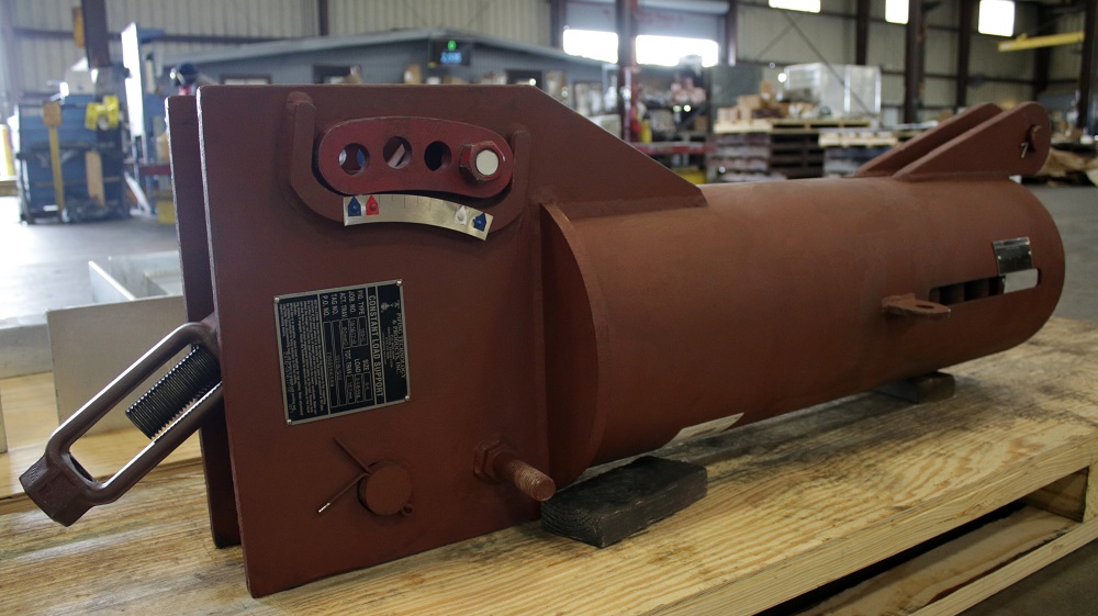
9/29/25: F-Type Constant Spring Supports Designed and Manufactured for Gas Plant
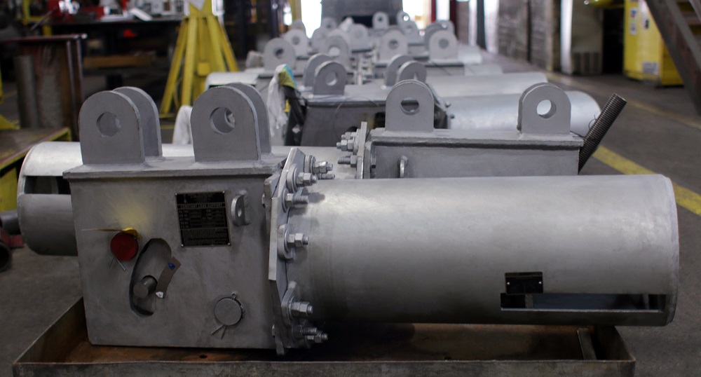
1/2/24: U-Type Constant Spring Supports Designed for a Power Plant
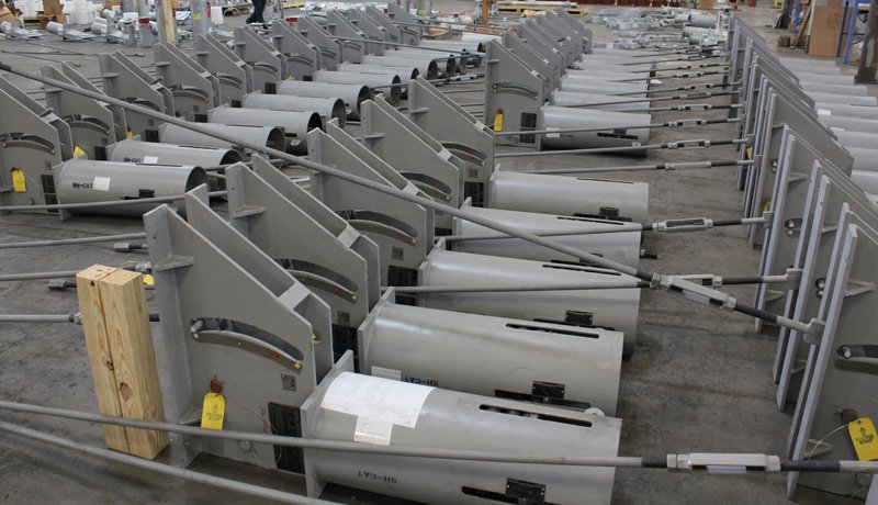
1/23/14: G Type Constant Spring Supports Designed for a Power Plant in Mississippi
12/15/09: Constant Spring Assemblies Custom Designed for Replacement of Failed Supports
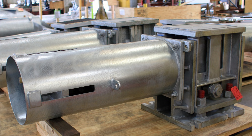
3/25/09: 200 U-Type Constant Spring Supports with Slide Plates to Reduce Friction
Request A Quote