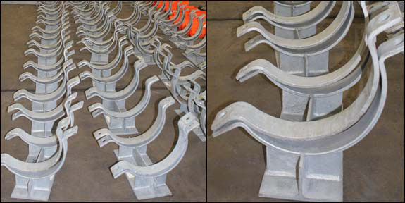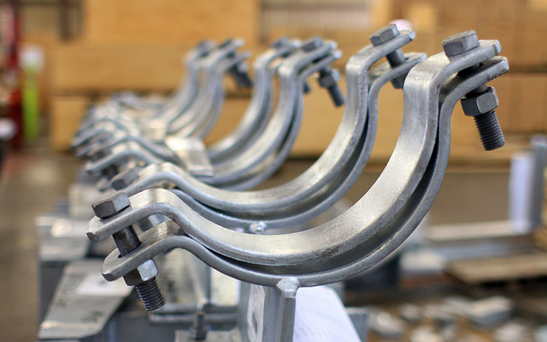
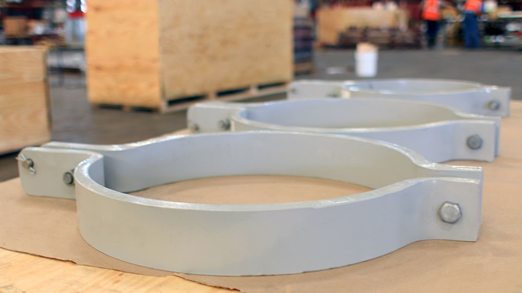
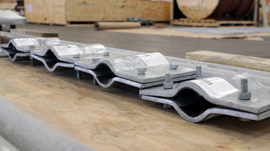
TYPES & SIZES
Technical Information
Methods of Protecting against Corrosion
Considering All Movement in Pipe Support Design
Comparative Corrosion Resistance Guide
Finite Element Analysis on a Pipe Clamp
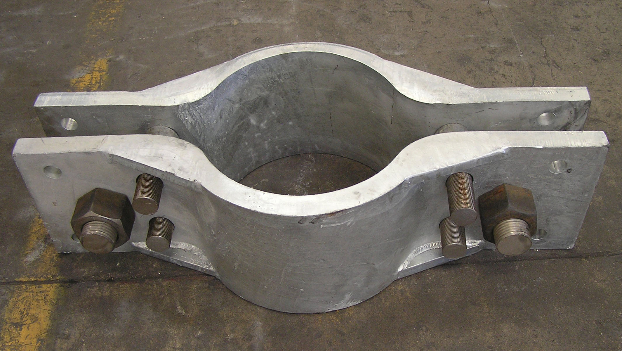
Exploring Plate Thickness of a Pipe Clamp
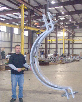
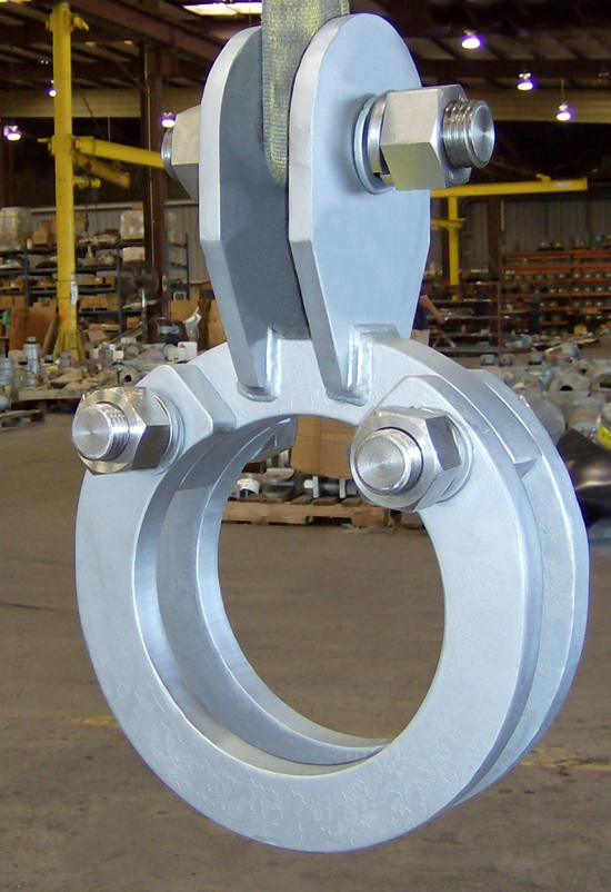
Support Assembly Components
Case Studies
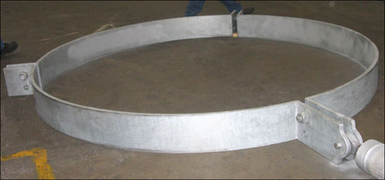
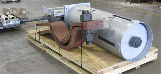
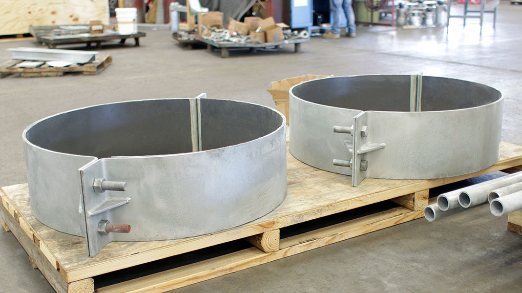
3/2/10: 22″ Dia. Riser Clamps for a Power Plant
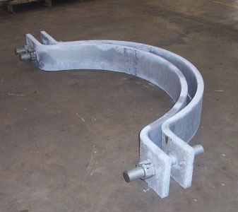
10/5/09: Riser Clamp for a 30″ Diameter Vertical Pipe at a Power Plant
9/29/09: Riser Clamps for 54″ FRP Pipe
4/4/07: Riser Clamps for a Power Plant in Rhode Island
Request a Quote