DynA/Damp: Models AD-40, AD-70, AD-150, AD-500, AD-500L
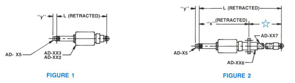
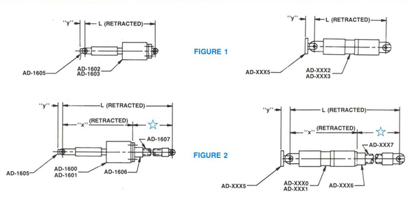
| Snubber Model | Stroke (Nominal) | Rated Load (Level A & B) | Figure-1 | Figure-2 | “X” | “Y”
|
L – Retracted
|
| L – Retracted | Min. | Max.
|
| AD-40 | 3″ | 400 LB. | 9 3/8″ | 14 7/8″ | 63″ | 8 21/32″ | 1 3/8″ |
| AD-70 | 4″ | 700 LB. | 11 21/32″ | 17 5/16″ | 62″ | 11 1/16″ | 1 3/8″ |
| AD-70R | 2 7/16″ | 700 LB. | 8 5/8″ | 13 5/8″ | 62″ | 7 1/2″ | 1 3/8″ |
| AD-150 | 4″ | 1500 LB. | 13 1/8″ | 19 3/4″ | 86″ | 12 17/32″ | 1 3/4″ |
| AD-150L | 8″ | 1000 LB. | 21 1/8″ | 27 3/4″ | 86″ | 20 17/32″ | 1 3/4″ |
| AD-500 | 4 7/8″ | 5000 LB. | 16 7/8″ | 24 5/8″ | 65″ | 15 7/8″ | 2 1/4″ |
| AD-500L | 9 7/8″ | 5000 LB. | 27 1/8″ | 34 7/8″ | 65″ | 26 1/8″ | 2 1/4″ |
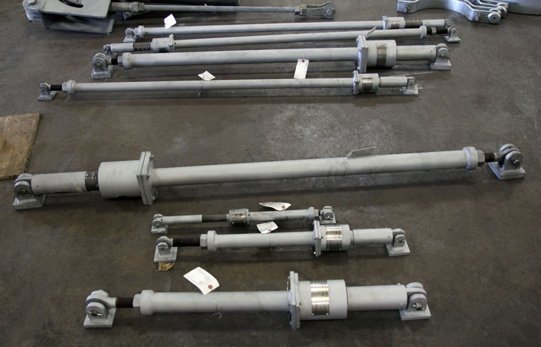
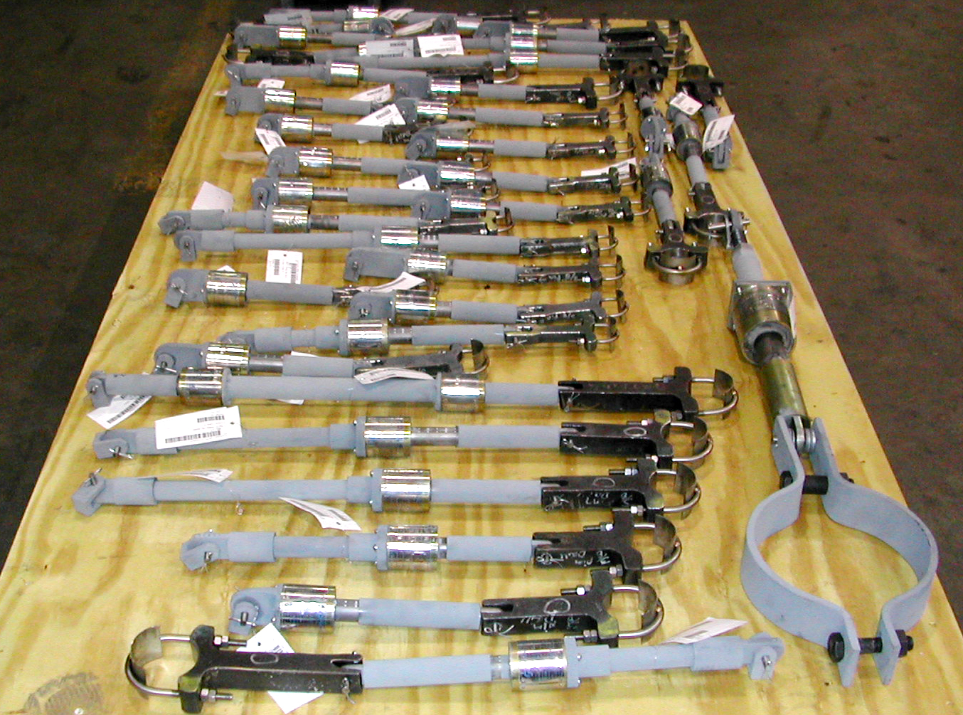
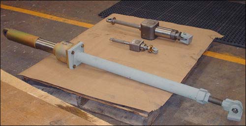
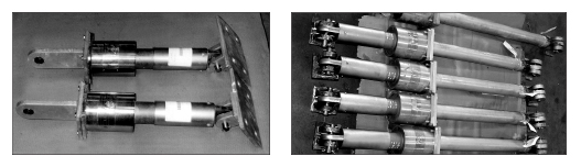
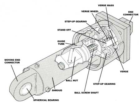
The dynA/damp® mechanical snubber design utilizes an oscillating verge with connecting gearing which limits the velocity of a geared rack and thereby controls the rate of linear displacement of piping or other equipment systems.
During normal thermal transients, the rack is free to displace with relatively small resistance. Upon introduction of an externally applied force — such as a seismic disturbance — oscillation of the verge limits movement of the geared rack to a velocity proportional to the applied load. Since the snubber is always engaged, instant snubbing action assures positive displacement control of the connected piping or equipment. This unique principle results in a rugged, simple device having a minimum number of moving parts.
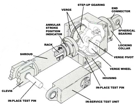
The dynA/damp® snubber consists of a housing assembly that encloses gearing, the verge system, and a reciprocating rack. The housing and the rack are connected to the pipe and the structure respectively. The gear and verge assembly are positively engaged at all times. Due to the mechanical nature of the system, the dynamic characteristics are constant and identical in extension or retraction.
dynA/Damp is a velocity limiting, mechanical snubber designed to protect critical power plant components during dynamic loadings caused by seismic disturbances or other transient forces. The dynA/Damp snubber has all the advantages of hydraulic dampening, without any of the drawbacks – it is a non-locking, velocity limiting device, that is always engaged and responds to dynamic disturbar jes instantly. Unlike other mechanical shock arresters, the dynA/damp® snubber is ruggedly designed and employs no complex clutches or spring mechanisms. It never needs lubrication or adjustment and can be easily tested in place.
The dynA/Damp snubber’s principle of operation, is simple and straight-forward. When a dynamic disturbance attempts to displace piping or equipment in either direction, an oscillatory type escapement mechanism restricts pipe movement to a constant velocity.
Gradual movements, such as those caused by changes in temperature, are virtually unrestricted. On the other hand, sudden movements which result from seismic disturbances, slamming of check valves, unstable pump characteristics, discharge of safety relief valves or water hammer are instantly dampened by providing a resistance proportional to the magnitude of the disturbance.
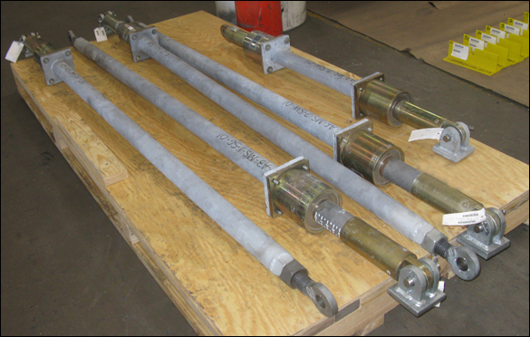
The superior operating principles of the dynA/Damp snubber combined with rugged, corrosion resistant construction make it extremely reliable. Designed for a forty-year service life, the dynA/Damp snubber is virtually unaffected by normal long-term, low amplitude vibration and provides dependable service over a wide range of loads and frequencies.
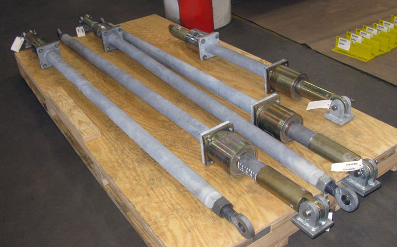
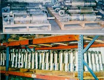
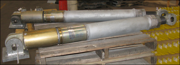
The larger sizes of the dynA/Damp mechanical snubber incorporate the same velocity limiting principle as our smaller rack and pinion designed snubbers.
Three oscillating verges set 120 apart, accept linear motion translated by a ball screw mechanism and step-up gearing. As in our smaller designs, the rate of linear displacement of piping system or equipment is controlled by means of this unique verge principle.
When an externally applied force such as a seismic disturbance is introduced, the simultaneous oscillation of three verges limits rotational movement of the ball screw shaft. This impedes the linear motion of the telescoping member by means of a directly coupled ball nut. The velocity attained is directly proportional to the applied load. The snubber remains always engaged and instantaneously reacts to assure positive displacement control of connected piping or equipment. The dynamic characteristics are also constant and identical in extension or retraction.
TRANSITION KIT LENGTH (L- (“X” + COLD SETTING))
large blue bar
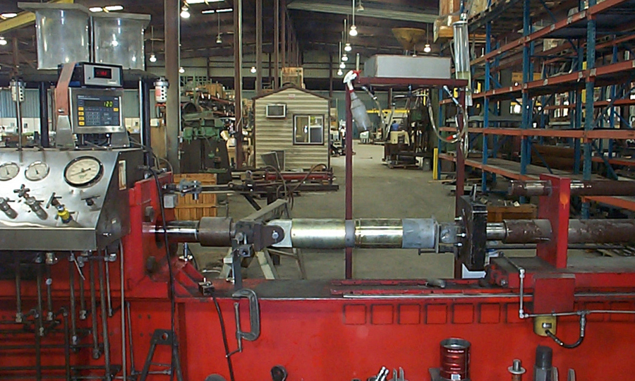
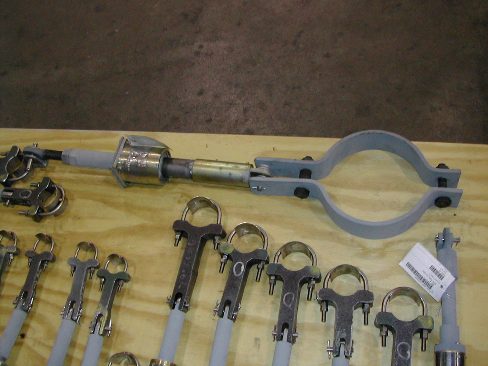
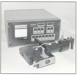
IN-PLACE SNUBBER TESTING
In response to the needs of the industry, Anchor/Darling designed the dynA/Damp® mechanical snubber with a unique, test-in-place option and developed the equipment necessary to permit utilities to perform operational testing on site, in location, using their own plant personnel. The equipment is designed to test, in situ, dynA/Damp® mechanical snubbers for operability based on the guidelines for testing recognized by the NRC and ANSI/ASME O & M 4.
The test-in-place tool consists of a solid-state control console, an electric drive head and adapters which allow for testing the complete line of dynA/Damp® snubbers. The console and drive head are connected by 100 feet of replaceable cable. For instant hard copy of the test data, a two-channel strip recorder, which records both RPM and torque is provided.
For additional information about dynA/Damp®’s exclusive in-place, time-saving test feature, contact your local Anchor/Darling sales representative today.
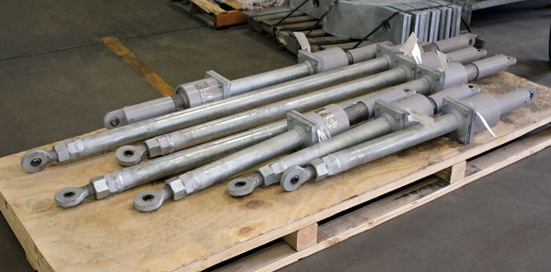
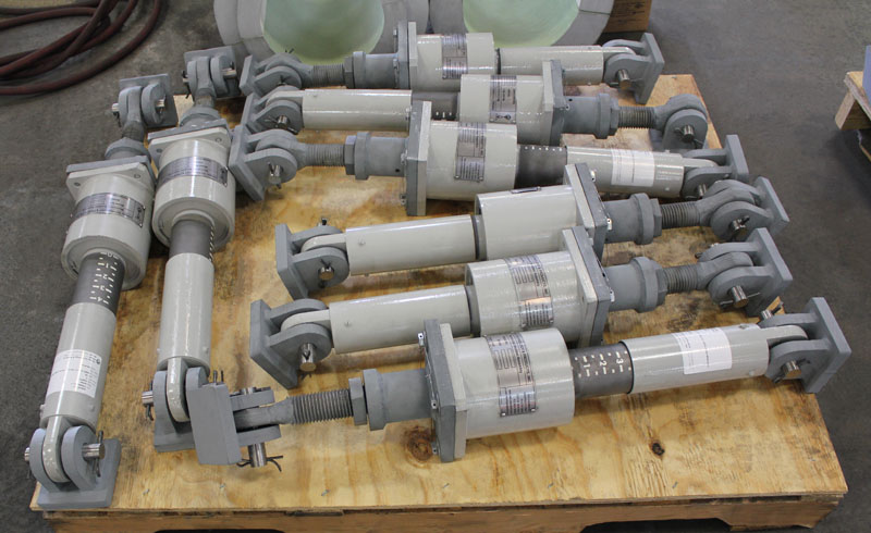
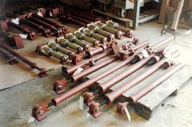
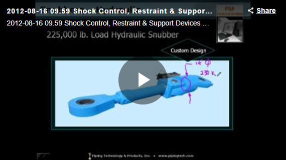
CUSTOM DESIGNED EQUIPMENT
Along with the standard dynA/Damp® mechanical snubber, Anchor/Darling can provide locking type mechanical snubbers for use as whip restraints for large pipes and vessels, as well as restraints for relief valve reaction forces. These snubbers are custom designed to fit your application — yet designed, tested, and supplied to you within lead times normally associated with standard equipment.
Equipment is available in loadings from 10 kip to 125 kip, with stroke and end connections to fit your applications. For more information on our equipment for special service, please contact either the regional office nearest you or our Laconia, New Hampshire office.