Variable Spring Supports

Variables use coiled springs to support a load and allow movement. The resistance of the coil to a load changes during compression, which is why these devices are called “variables”. We offer a variety of different designs of variable spring pipe supports.

Variable Spring Supports Details

Request A Quote


Acid Plants
Aerospace Development
Chemical Plants
Cogeneration Plants

Coker Units
Furnace Ammonia
Gasoline Production & Storage
Liquified Natural Gas

Natural Gas Processing & Separation
Offshore Platforms
Oil Sands Mines
Paper Manufacturing

Petroleum Facilities
Power Plants
Solar Electric Generating
See More

Variable springs always must have a difference in load between the hot and cold settings. Whereas in constant springs, the ...Continue Reading

A spring hanger is a subset of either variable or constant spring supports that attach directly to structural steel components ...Continue Reading

The “cold” setting of a variable spring support refers to the installed position and the associated load being carried by ...Continue Reading

We offer seven different configurations for Variable Spring Supports (Type A, B, C, D, E, F, G). Click here for ...Continue Reading

“Spring can” is the general term used to describe either variable or constant spring supports. Custom Spring Can with Slide ...Continue Reading

It would not be recommended for a constant spring to be designed for less than 0.1″ for travel. Variable springs ...Continue Reading


More FAQs…

General Dimensions & Specifications

PT&P has set up it's manufacturing to offer an unparalleled set of customization options with minimal impact on delivery timeframes. In addition to our standard (hot-dipped galvanized, neoprene lined springs) variable spring supports, we can customize any material, finish, dimension, load, load adjustment, travel, travel stops, as well as providing sensors for remote monitoring. View more details on how we can customize your variable spring support.

Download Variable General Information

INDUSTRY STANDARDS AND SPECIFICATIONS

The Manufacturers Standardization Society (MSS) has standard practices SP-58 and SP-69 which are widely used in our industry. ASME B31.1 and B31.3 are important standards for piping in the power and petrochemical industries. Moreover, many of our customers have their own standards and designs for pipe supports. At Piping Technology & Products, Inc., we always keep these guidelines in mind and manufacture your supports to their strict specifications. In this section, you will find our standard variable and constant pipe supports.

TYPES OF VARIABLE SUPPORTS

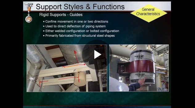
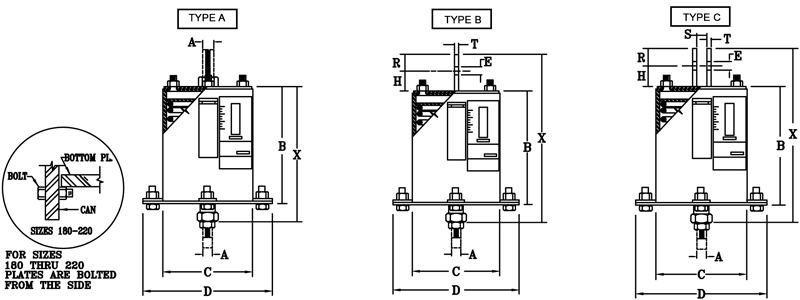
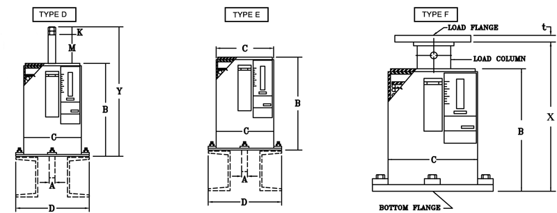
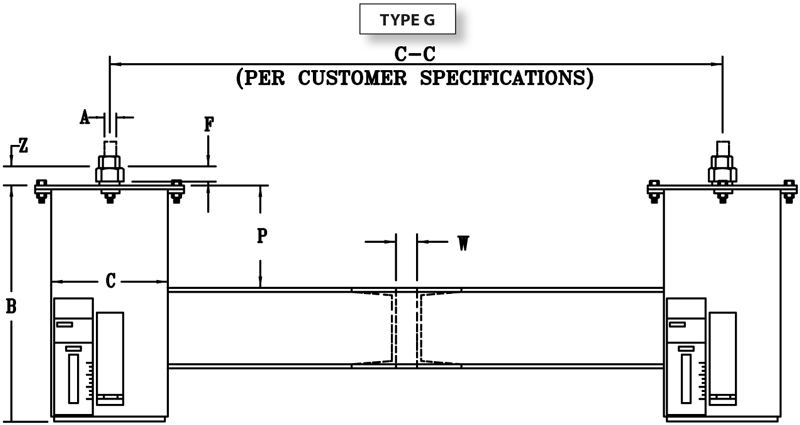
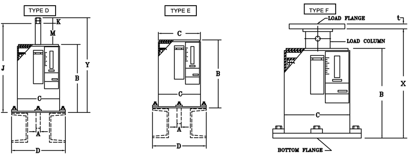
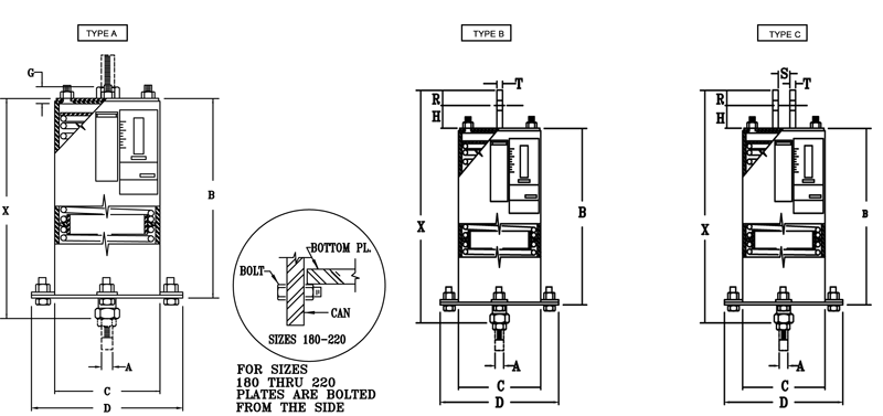
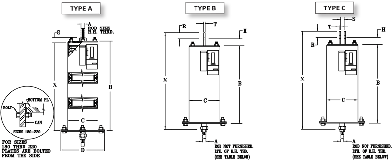
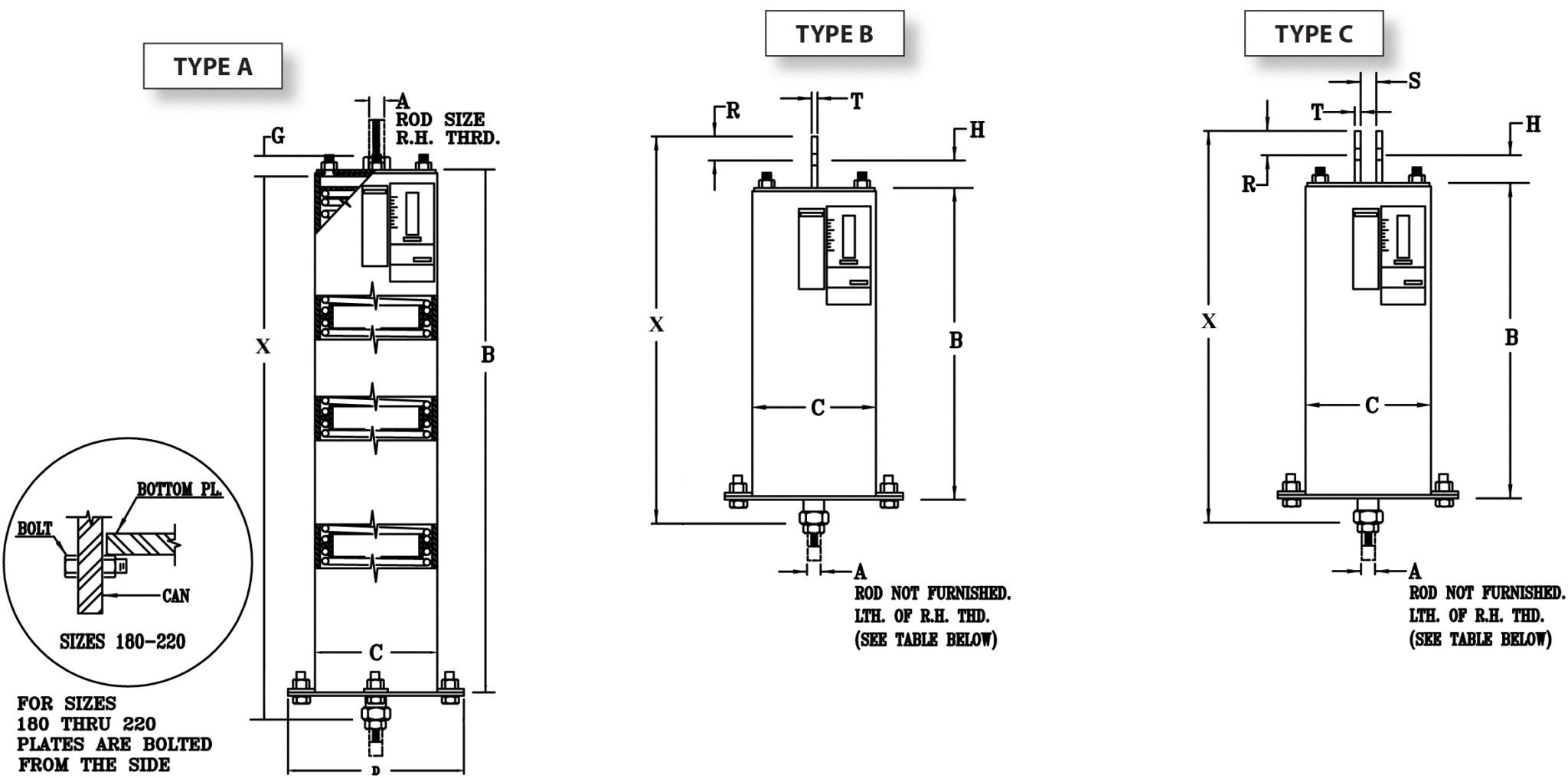
The term “type” is used with an alphabetical designation (A-G) to describe seven different physical connections to the supporting structure. The figure below illustrates the applications and the physical connections for each type. Hangers are suspended from structural members while base supports (Type F) rest on a supporting surface.

Variable Spring Support Types

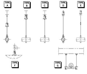
Type A: The spring support is furnished with a threaded bushing in the top plate, providing for a simple rod attachment for the upper connection.
Type B & C: The spring supports are furnished with one or two lugs welded to the top cap plates of the casing.
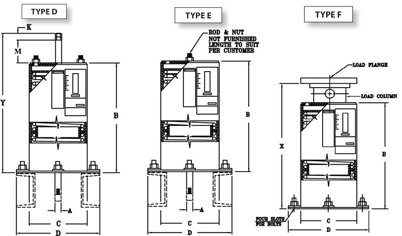
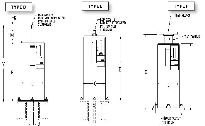
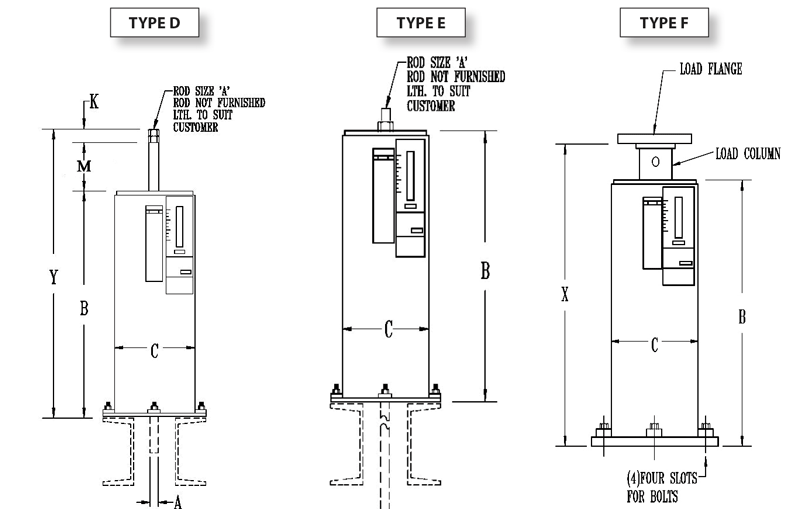
Type D: The spring support permits adjustment from the top, by turning the nuts on the hanger rod against a piece of tubing. The tubing is securely welded to the spring cap. In type D, the spring is set above the supporting steel.
Type E: The spring support permits rod adjustment from either above or below the spring. The type E spring is set above the supporting steel or can be welded directly to the supporting steel from below.
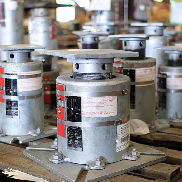
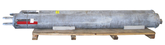
Type F: The spring support is designed to support piping from below, directly from the floor or supporting steel. Adjustment is made by inserting a bar into holes in the load column and turning the load column as a jackscrew. The base plate is bolted to the case and has four holes for fastening. The installed height of the base (F-type) spring should be specified as follows:

• With upward movement from cold to hot position: The installed height should be the midpoint between the minimum and maximum “X” dimension plus the thickness of the load flange.
• With downward movement from cold to hot position: The installed height should be the midpoint between the minimum “X” dimension plus the load flange thickness plus the amount of the vertical movement.

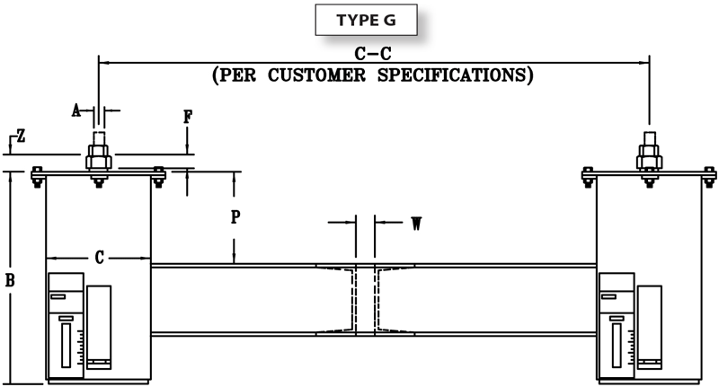
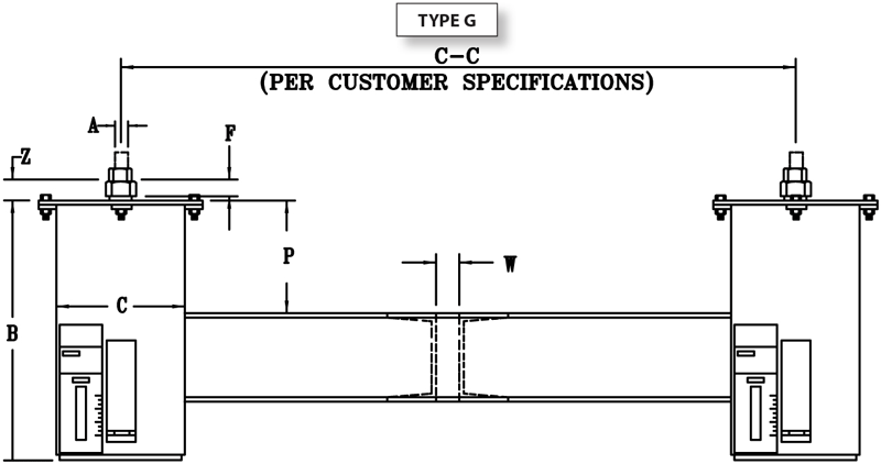
Type G: The spring support assembly is formed by welding two standard spring assemblies to the ends of a pair of channels. Type G assembly can accommodate unusually heavy loads and is especially adaptable for avoiding interference in spaces where the headroom is limited. The assembly can be furnished with center-to-center dimensions, as specified by the purchaser. When ordering Type G, divide the total pipe load in half to select the proper spring size. The travel range of the springs remains unchanged.

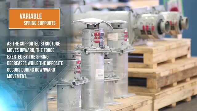
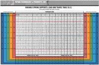
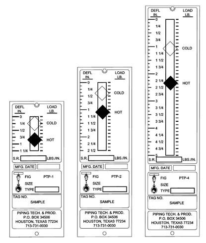
The way a variable spring support responds to an applied load depends on the coil or coils inside the casing. Each coil arrangement has a spring rate expressed in units of pounds/inch (or kilograms/millimeters) of compression. The required coil size is determined by load while the required number of coils (length) is determined by the anticipated range of movement. A longer coil or coils placed in series will provide greater travel for similar loads. Manufacturers use their figure numbers to designate the coil arrangements which provide greater movement. At Piping Technology & Products, Inc., we use PTP-1, PTP-2, PTP-4, PTP-6, and PTP-8 to designate the five standard coil arrangements we employ to increase the working range of travel of variable supports. The Load and Travel Tables are color-coded to identify the travel and spring rates for each PTP figure number. These tables can be used to select the PTP figure number and size required for a particular application.

PHYSICAL DIMENSIONS
The physical dimensions of variables are different depending on the figure number and size you have selected. The following pages provide drawings and dimensions for every combination of PTP’s standard variable supports. If you have a requirement for which you do not have clearance for the standard spring, please contact us about a modification to satisfy your requirement.
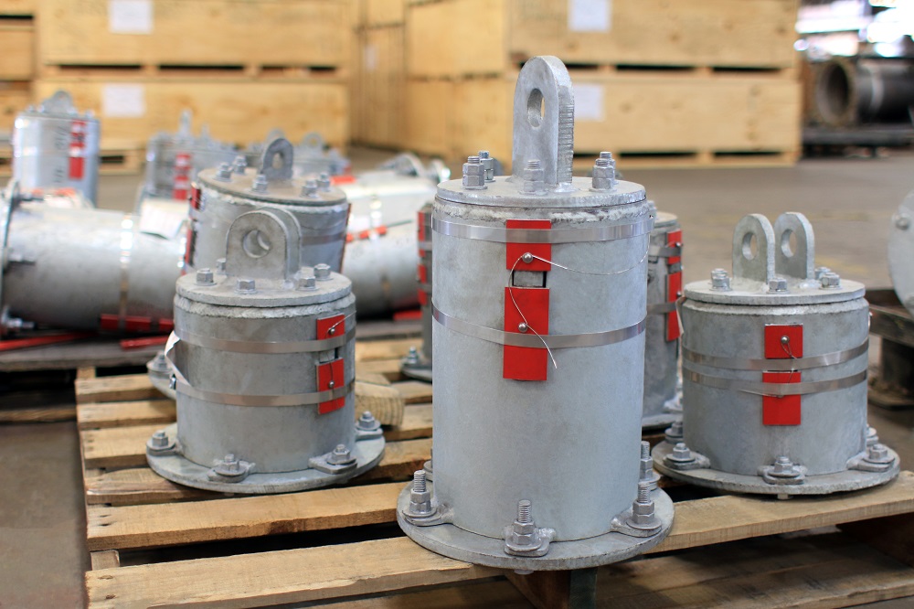
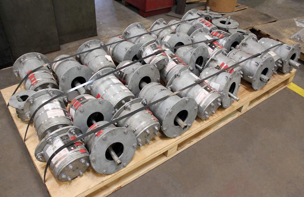
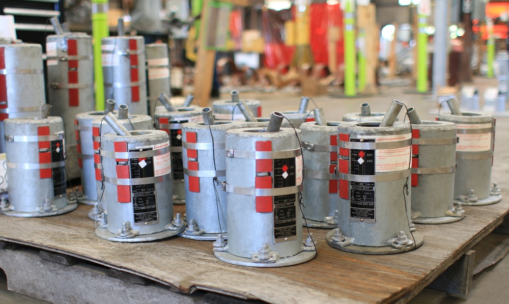
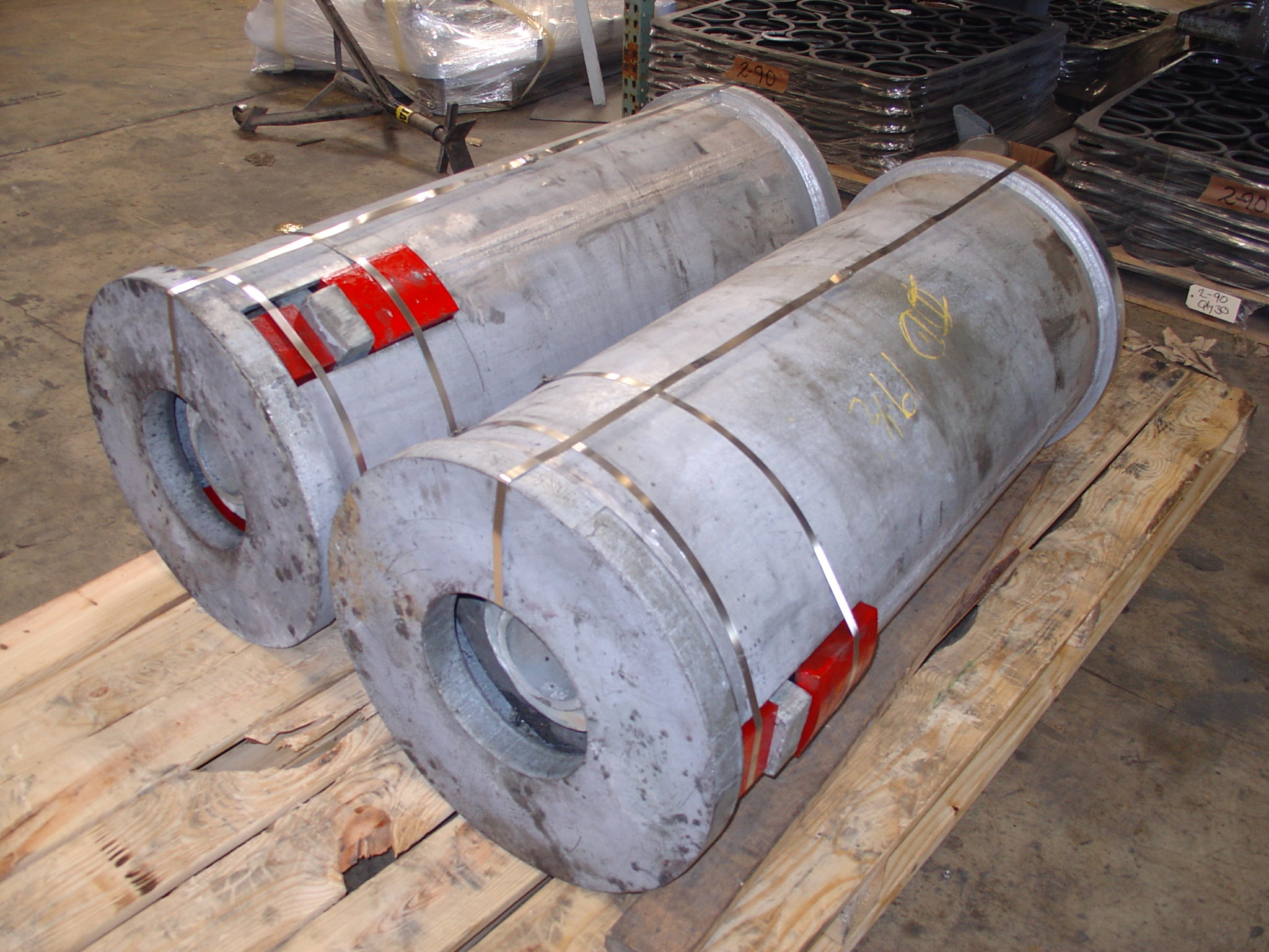
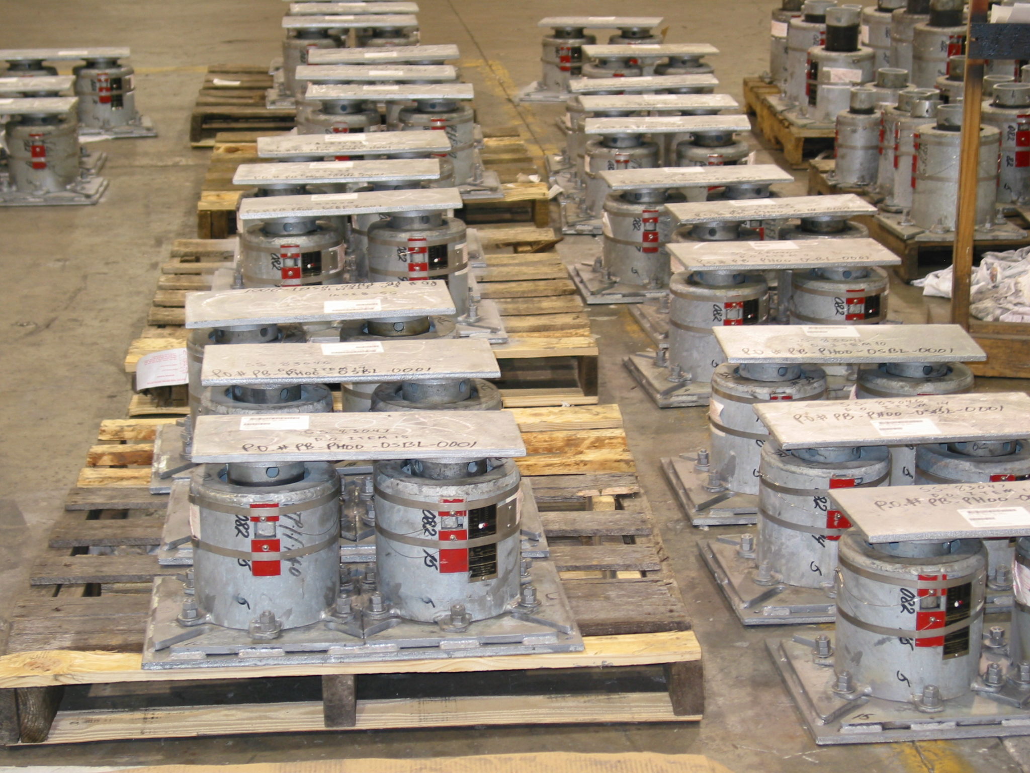
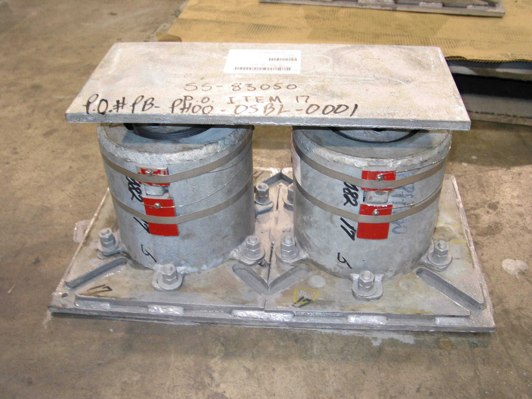
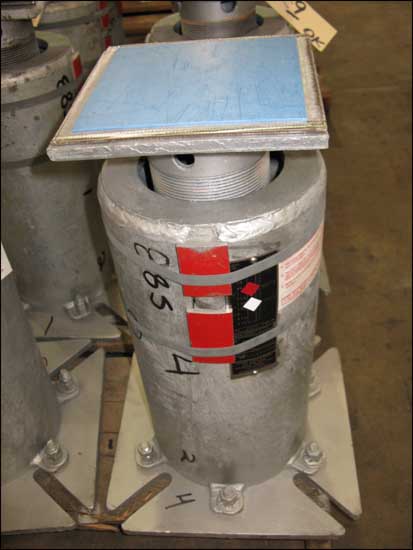
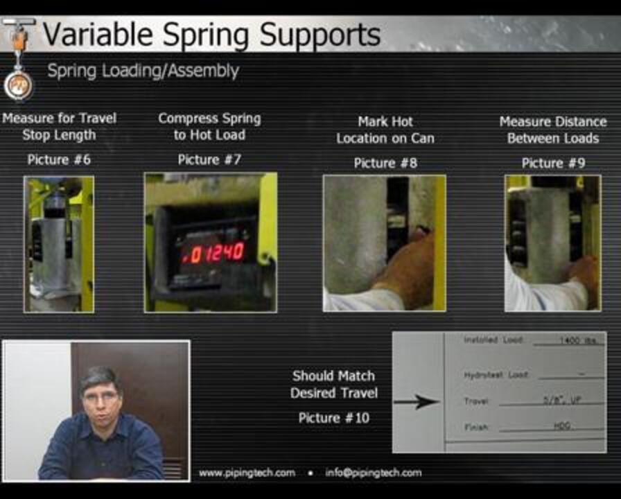
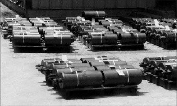
During assembly the coils are pre-compresseVariable Spring Support Travel Stops
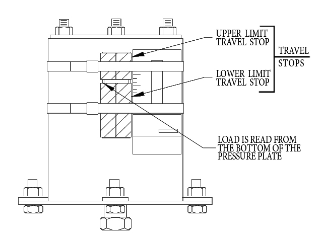
d and travel stops, which are painted red, are installed and banded in place with steel bands as shown in the figure to the right. Any load, such as in hydro-testing of the pipe, applied to the variable spring prior to removing the travel stops will not be applied to the coil. When the installation is complete, the travel stops must be removed so the variable spring can function properly.

FINISH
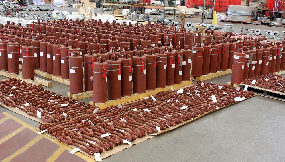
Galvanizing provides the most cost-effective finish for use in corrosive environments. Because the majority of our customers specify galvanized finish, we maintain a large inventory of galvanized components which enables us to assemble and ship variables very quickly. A longer delivery time may be required when finishes other than galvanized are specified.

SPECIAL FEATURES
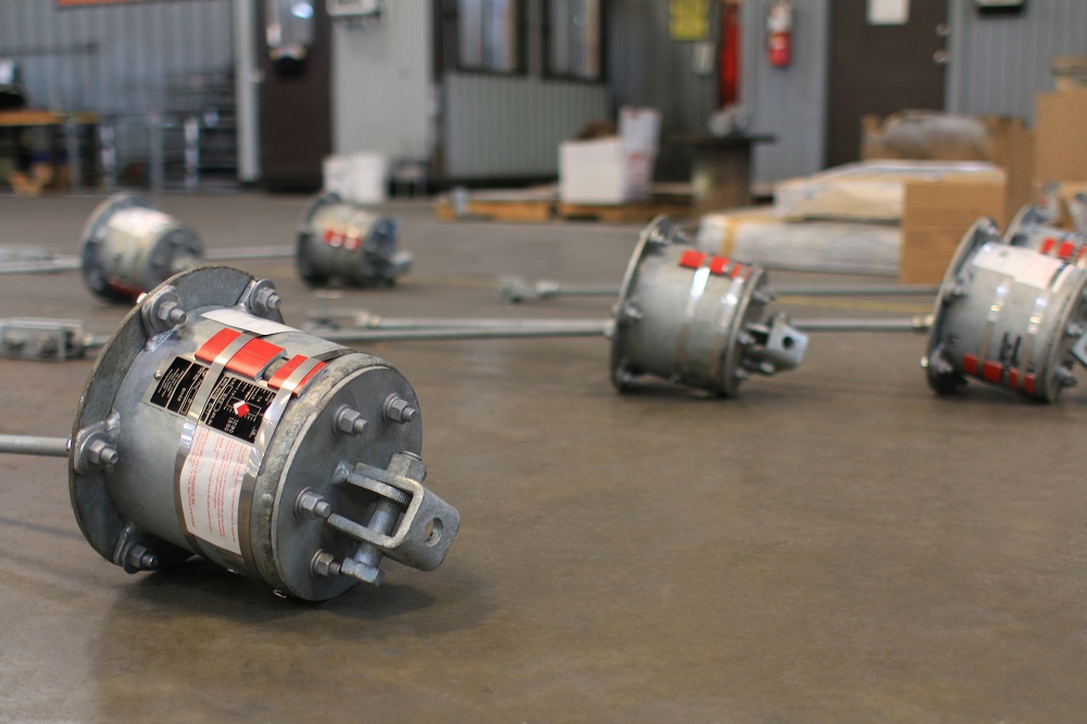
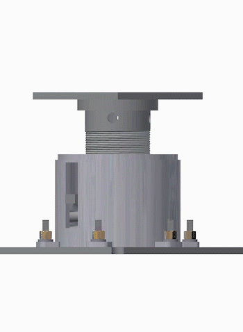
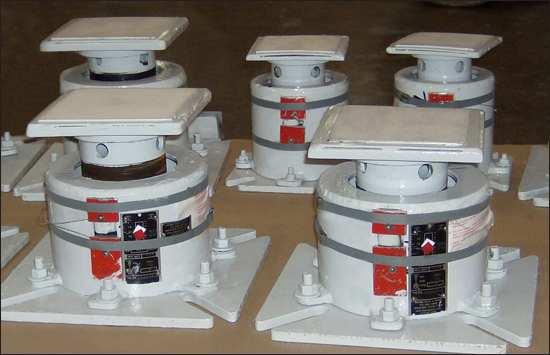
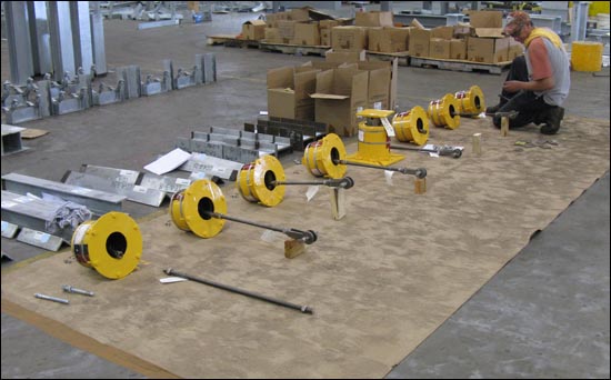
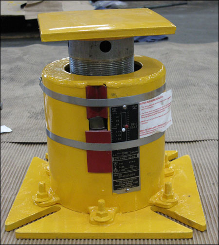
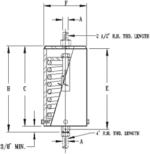
Special features can be provided with the PT&P standard variables when required. For example, lifting lugs, such as those shown in the figure on the right, can be helpful for installing large hangers. Other special features include upper and lower limit stops, guided load columns, jacking bolts, PTFE 25% glass filled slide plates, collars or extended load columns. Special features may increase the price and the time required for delivery.
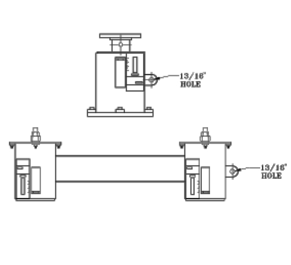
Variable Spring Support Hole Size

FEATURES
1. Precompression – precompressing the spring coil into the hanger casing saves headroom and erection time.
2. Slots in the casing at two locations 180 degrees apart allowing for complete in-service visual inspection of the spring coil and other internal components.
3. For each series, there is a reserve travel at the upper and lower limits of the working range of the hanger, and any travel beyond this reserve travel becomes either free up movement or a limit stop for downward travel.
4. The allowable stress of the coil spring conforms to MSS SP-58.
5. All-steel construction-spring and casing are fabricated of steel and are rugged and compact.
6. Anti-corrosive material (stainless steel) is used for the nameplate.
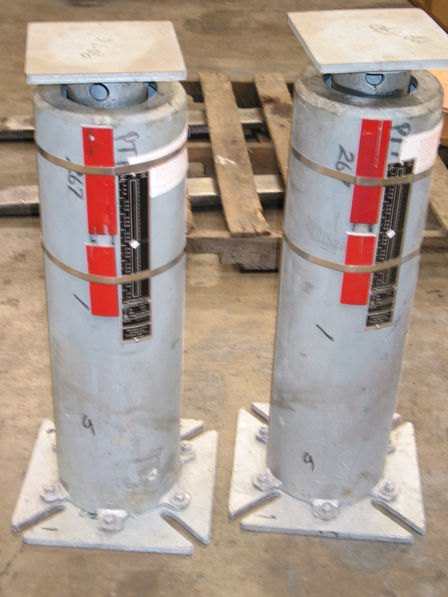
7. Load Indicators are clearly visible in the slot and are easily readable.
8. The piston plate serves as a centering device or guide, maintaining spring concentricity under eccentric loads.
9. The finish is hot-dipped galvanized, or other, as specified.
10. All F-type supports are supplied with a load flange.

 Variable load table thumbnail Variable Load & Travel Tables
Click on the above PDF to view the load and travel tables in Standard, Metric, and Newton.

The twenty-three columns designed 00, 10, 20, …, 220 identify the size and spring rate of coils used in the variables. The larger numbers have higher spring rates and are used to support greater loads. The recommended working range of loads for each size is shown between the red lines in the tables. The center of the working range is colored blue. Selecting variables with the loads within the working range provides a reserve above and below to ensure the coil can function inside the casing. In using the Load and Travel Table to choose the proper variable support, it is best to have the operating (hot) load and an amount and direction of expected movement. Variability is a key criterion in selecting the figure number and size. Variability is the percentage of change in the supporting force between the operating (hot) and installed (cold) positions calculated as shown:

Variability = (Spring Rate x Movement) / Operating Load

Good practice, as specified by MSS SP-58, is to choose a support with variability less than or equal to 25%.

Always try to choose a variable with the operating (hot) load near the centerline (blue) of the working range in the Load and Travel Table. If you have a situation in which you cannot select a standard variable which has both the operating load and the installed load within the working range, contact us and we will help you determine alternatives.

The quality of the spring coil is very important to performance. Piping Technology buys coils from major suppliers with automated production facilities and Quality Assurance programs to provide the highest quality at competitive prices. We keep an extensive inventory of coils at all times so we can respond to the emergency requirements of our customers.

Most of our customers request neoprene coating for their spring coils, which we do in our facility. Neoprene protects the spring coil from many corrosives without affecting the flex life of the coil. In some cases, such as in a furnace installation, temperatures are too high for neoprene. We apply paint or other types of coatings for this situation. Neoprene is recommended only for operating temperatures up to 255°F.

Each variable spring we build is placed in a load cell and calibrated to the design load and movement. The nameplates show the position where the pressure plate meets the coil at the operating (hot) load and the installed (cold) load positions. The nameplate also shows PTP’s figure number, size, spring rate, and the customer’s designated mark or tag number.

 spring name plates

SPRING NAME PLATES

Download PDF

Fig. PTP-1 – Types A, B, & C – Short Variable Springs

Fig. PTP-1-Types A, B, & C-Short Variable Springs
ORDERING: Specify figure number, size, type, description, operating load and calculate amount & direction of pipe movement from installed to operating position. Please specify any non-standard requirements, i.e. internally guided load column, jacking bolt, lifting lugs, etc.

GENERAL DIMENSIONS FOR FIG. PTP-1 TYPE ATYPES B & CTYPES A, B, & C
HANGER SIZEROD SIZECASING DIA.BOTT. PLATE. DIA.CASING LENGTHLOADED LENGTH XCASING LENGTHLUG HOLE SIZEHEIGHT OF PINCLEVIS OPENINGTHICKNESSLOADED LENGTH XAPPROX. WEIGHT OF EACH
ACDBMIN.MAX.BEHRSTMIN.MAX.lb.
001/246  1/84  7/85  11/166  15/164  7/811/161  1/21  1/47/81/48  7/169  11/165
101/246  1/85  1/85  7/87  1/85  1/811/161  1/21  1/47/81/48  5/8 9  7/8 6
201/246  1/85  3/4 6  9/167  13/16 5  3/4 11/161  1/21  1/47/81/49  5/16 10  9/16 7
301/25  9/167  5/85  1/4 6  1/87  3/8 5  1/4 11/161  1/21  1/47/81/48  7/8 10  1/8 9
401/25  9/167  5/85  5/86  5/16 7  9/16 5  5/8 11/161  1/21  1/47/81/49  1/16 10  5/16 10
501/25  9/167  5/866  7/8 8  1/8 611/161  1/21  1/47/81/49  5/8 10  7/8 11
605/86  5/8 8  7/867  3/16 8  7/16 613/16 1  1/21  1/41  1/161/49  15/16 11  3/16 17
705/86  5/8 8  7/8 6  5/87  7/89  1/8 6  5/8 13/16 1  1/21  1/41  1/161/410  5/8 11  7/8 20
805/86  5/8 8  7/86  7/88  1/4 9  1/2 6  7/8 13/16 1  1/21  1/41  1/161/411 12  1/4 21
903/48  5/8 11  5/8 7  1/48  1/89  3/8 7  1/4 15/16 1  1/21  1/41   1/4 3/810  7/8 12  1/8 46
1003/48  5/8 11  5/8 7  3/48  7/169  11/16 7  3/4 15/16 1  1/21  1/41  1/4 3/811  3/16 12  7/16 52
1103/48  5/8 11  5/86  7/168  1/89  3/8 6  7/16 15/16 1  1/21  1/41  1/4 3/810  7/8 12  1/8 45
12018  5/8 11  5/87  1/89  1/16 10  5/16 7  1/8 1  1/4 21  1/21  5/8 1/2 12  9/16 13  13/16 48
13018  5/8 11  5/88  1/2 9  3/411 8  1/2 1  1/4 3 1  1/21  5/8 1/2 13  1/4 14  1/2 59
1401  1/48  5/8 11  5/8910  1/211  3/4 91  1/2 3 225/8 15  1/2 16  3/4 62
1501  1/48  5/8 11  5/88  7/811  5/1612  9/16 8  7/8 1  1/2 3 225/8 16  5/16 17  9/16 74
1601  1/28  5/8 11  5/8 10  1/213  1/214  3/4 10  1/2 1  3/4 3 2  1/2 2  3/8 3/4 1920  1/4 88
1701  3/48  5/8 11  5/8 11  3/415  9/1616  13/16 11  3/4 23 2  1/2 2   3/8 3/4 2  11/16 22  5/16 106
180212  3/4 N/A1517  1/818  3/8 152  3/8 432  7/8 3/4 24  1/8 25  3/8 229
1902  1/412  3/4 N/A 1618  3/8 19  5/8 162  5/8 4  1/2 33  1/8 3/4 25  7/8 27  1/8 256
2002  1/212  3/4 N/A2022  3/823  5/8 202  7/8 4  1/2 43  1/4 1 30  7/8 32  1/8 320
2102  3/412  3/4 N/A20  5/823  1/4 24  1/2 20  5/8 3  1/8 4  1/2 43  5/8 1 31  3/4 33371
220312  3/4 N/A24  7/827  3/4 29 24  7/8 3  3/8 543  7/8 1 36  3/4 38 460

Download PDF

Fig. PTP-1 – Types D, E, & F – Short Variable Springs

Fig. PTP-1-Types D, E, & F-Short Variable Springs
ORDERING: Specify figure number, size, type, description, operating load and calculate amount & direction of pipe movement from installed to operating position. Please specify any non-standard requirements, i.e. internally guided load column, jacking bolt, lifting lugs, etc.

HANGER SIZETYPES D & ETYPE F
CASING LENGTH ROD LENGTH NUT ALLOW. SPACER HEIGHT
APPROX. WEIGHT
OF EACH
CASING LENGTH BOTTOM FLANGE
BOTTOM FLANGE BOLT CIRCLE BOTTOM FLANGE
LOAD COLUMN
LOAD FLANGE
LOADED LENGTH X APPROX. WEIGHT
BYKMlb.BTHK. x SQ. MIN. MAX. BOLTSDIA.THK. x SQ. MIN. MAX. lb.
004  5/8 7  1/2 1  1/41  3/4 44  5/8 1/4 x 7  1/2 7 8  3/4 5/81.900 3/16 x 3  13/16
6  3/16 6  11/16 10
104  7/8 7  3/4 1  1/41  3/4 54  7/8 1/4 x 7  1/2 7 8  3/4 5/81.900 3/16 x 3  13/16
6  7/16 6  15/16 10
205  1/2 8  3/8 1  1/41  3/4 65  1/2 1/4 x 7  1/2 7 8  3/4 5/81.900 3/16 x 3  13/16
7  1/16 7  9/16 11
305 7  7/8 1  1/41  3/4 85 1/4 x 7  1/2 7  3/4 8  3/4 3/42.875 3/16 x 5  1/4
6  9/16 7  1/16 17
405  3/8 8  1/4 1  1/41  3/4 95  3/8 1/4 x 7  1/2 7  3/4 8  3/4 3/42.875 3/16 x 5  1/4
6  15/16 7  7/16 18
505  3/4 8  5/8 1  1/41  3/4 105  3/4 1/4 x 7  1/2 7  3/4 8  3/4 3/42.875 3/16 x 5  1/4
7  5/16 7  13/16 19
605  3/4 9  1/16 1  1/21  3/4 165  3/4 3/8 x 9 8  1/8 10  7/8 3/43.501/4 x 6  5/16
7  5/16 7  13/16 30
706  3/8 9  11/16 1  1/21  3/4 19 6  5/8 3/8 x 9 8  1/8 10  7/8 3/43.501/4 x 6  5/16
7  15/16 8  7/16 32
806  5/8 9  15/16 1  1/21  3/4 206  3/8 3/8 x 9 8  1/8 10  7/8 3/43.501/4 x 6  5/16
8  3/16 8  11/16 33
90711  1/4 1  3/41  3/4 4271/2 x 13  1/4 12  1/4 16  1/2 3/44.50 1/2 x 8  1/4
8  9/16 9  9/16 68
1007  1/2 11  3/4 1  3/41  3/4 487  1/2 1/2 x 13  1/4 12  1/4 16  1/2 3/44.50 1/2 x 8  1/4
9  1/16 10  1/16 74
1106  3/16 10  11/16 21  3/4 416  3/16 1/2 x 13  1/4 12  1/4 16  1/2 3/44.50 1/2 x 8  1/4
7  3/4 8  3/4 66
1206  3/4 11  1/4 2  1/41  3/4 436  3/4 1/2 x 13  1/4 12  1/4 16  1/2 3/44.50 1/2 x 8  1/4
8  5/16 9  5/16 68
1308  1/8 12  7/8 2  1/2 1  3/4 538  1/8 1/2 x 13  1/4 12  1/4 16  1/2 3/44.50 1/2 x 8  1/4
9  11/16 10  11/16 71
1408  5/8 13  1/8 2  1/2 1  3/4 558  5/8 1/2 x 13  1/4 12  1/4 16  1/2 3/44.50 1/2 x 8  1/4
10  3/16 11  3/16 81
1508  1/2 14  1/8 31  3/4 658  1/2 1/2 x 13  1/4 12  1/4 16  1/2 3/44.50 1/2 x 8  1/4
10  1/16 11  1/16 86
16010 15  7/8 3  1/2 1  3/4 7710 1/2 x 13  1/4 12  1/4 16  1/2 3/44.50 1/2 x 8  1/4
11  9/16 12  9/16 98
17011  1/4 17  5/8 4 1  3/4 9111  1/4 1/2 x 13  1/4 12  1/4 16  1/2 3/44.50 1/2 x 8  1/4
12  13/16 13  13/16 112
18014  3/8 19  3/16 4  9/16 1  3/4 19611  7/8 5/8 x 17  1/4
17  3/4 22 3/45.563 1/2 x 12  1/213  7/16 14  7/16 240
19015  3/8 20  5/8 5 1  3/4 21612  7/8 5/8 x 17  1/4
17  3/4 22 3/45.563 1/2 x 12  1/2
14  7/16 15  7/16 245
20019  1/4 23  5/16 5  9/16 1  3/4 27215  5/8 3/4 x 17  1/4
17  3/4 22 3/45.563 1/2 x 12  1/2
17  3/16 18  3/16 314
21019  7/8 25 6  1/4 1  3/4 30916  1/4 3/4 x 17  1/4
17  3/4 22 3/45.563 1/2 x 12  1/2
17  13/16 18  13/16 318
22024  1/8 29  5/8 6  5/8 1  3/4 40120  1/2 3/4 x 17  1/4
17  3/4 22 3/45.563 1/2 x 12  1/2
22  1/16 23  1/16 413

Download PDF

Fig. PTP-1 – Type G – Short Variable Springs

Fig. PTP-1-Type G-Short Variable Springs
ORDERING: Specify figure number, size, type, description, operating load and calculate amount & direction of pipe movement from installed to operating position. Please specify any non-standard requirements, i.e. internally guided load column, jacking bolt, lifting lugs, etc.

HANGER SIZE TYPE G
APPROX. WEIGHT OF EACH ROD SIZE CASING LENGTH CASING DIAMETER MINIMUM THREAD ENGAGE-MENT MAX. PIPE SIZE MAX. C-C DIM. CHANNEL SIZE SPACING BETWEEN CHANNELS PZ
lb.ABCFW
00251/24  5/847/81224C 3 x 4.15/811  1/16
10251/24  7/847/81224C 3 x 4.15/811
20271/25  1/247/81224C 3 x 4.15/811  1/16
30291/255  9/167/81630C 3 x 4.13/411  1/8
40311/25  3/85  9/167/81630C 3 x 4.13/4115/16
50321/25  3/45  9/167/81630C 3 x 4.13/411  1/8
60455/85  3/46  5/81  1/162036C 3 x 4.1121  7/16
70515/86  3/86  5/81  1/162036C 3 x 4.1121  1/2
80535/86  5/86  5/81  1/162036C 3 x 4.1121  5/8
901053/478  5/81  5/162036C 4 x 5.41  1/421  1/4
1001173/47  1/28  5/81  5/162036C 4 x 5.41  1/421  1/16
1101013/46  3/168  5/81  5/162036C 4 x 5.41  1/422  1/16
12011216  3/48  5/81  9/162036C 5 x 6.71  1/21  1/22  5/16
13013418  1/88  5/81  3/42036C 5 x 6.71  1/231  5/8
1401391  1/48  5/88  5/81  3/41633C 5 x 6.71  1/231  7/8
1501721  1/48  1/28  5/81   7/82036C 6 x 10.52  1/812  15/16
1602021  1/2108  5/82  3/162036C 8 x 11.52  1/823  1/2
1702381  3/411  1/48  5/82  7/162036C 8 x 11.52  1/824  5/16
180488214  3/812  3/42  13/162042C 12 x 20.72  3/81/22  5/8
1905392  1/415  3/812  3/43  1/162042C 12 x 20.72  5/812  7/8
2006692  1/219  1/412  3/43  5/162040C 12 x 20.72  7/812  7/8
2108272  3/419  7/812  3/43  11/162448C 15 x 33.93   1/813  1/8
2201006324  1/812  3/43  15/162448C 15 x 33.93  3/833  3/8

Download PDF

Fig. PTP-2 – Types A, B, & C – Standard Variable Springs

Fig. PTP-2-Types A, B, & C-Standard Variable Springs
ORDERING: Specify figure number, size, type, description, operating load and calculated amount and direction of pipe movement from installed to operating position. Please specify any non-standard requirements, i.e. internally guided load column, jacking bolt, lifting lugs, etc.

GENERAL DIMENSIONS FOR FIG. PTP-2 TYPE ATYPES B & CTYPES A, B & C
HANGER SIZE ROD SIZE CASING DIAMETER BOTT. PLATE DIA. CASING LENGTH LOADED LENGTH X CASING LENGTH LUG HOLE SIZE HEIGHT OF PIN CLEVIS OPENING THICKNESS LOADED LENGTH X APPROX. WEIGHT OF EACH
ACDBMIN.MAX.BEHRSTMIN.MAX.lb.
001/246  1/87  1/47  9/1610  1/167  1/411/161  1/21  1/47/81/410  5/1612  13/167
101/246  1/88  3/328  5/1610  13/168  3/3211/161  1/21  1/47/81/411  1/1613  9/168
201/246  1/88  7/89  1/1611  9/168  7/811/161  1/21  1/47/81/411  13/1614  5/169
301/25  9/167  5/87  15/168  7/1610  15/167  15/1611/161  1/21  1/47/81/411  3/1613  11/1612
401/25  9/167  5/88  1/28  3/411  1/48  1/211/161  1/21  1/47/81/411  1/21414
501/25  9/167  5/89  1/49  5/812  1/89  1/411/161  1/21  1/47/81/412  3/814  7/815
605/86  5/88  7/89  3/169  11/1612  3/169  3/1613/161  1/21  1/41  1/161/412  7/1614  15/1624
705/86  5/88  7/810  1/810  3/413  1/410  1/813/161  1/21  1/41  1/161/413  1/21627
805/86  5/88  7/810  5/811  1/413  3/410  5/813/161  1/21  1/41  1/161/41416  1/229
903/48  5/811  5/810  11/1612  1/414  3/410  11/1615/161  1/21  1/41  1/43/81517  1/256
1003/48  5/811  5/811  7/81315  1/211  7/815/161  1/21  1/41  1/43/815  3/418  1/462
1103/48  5/811  5/89  11/1611  7/1613  15/169  11/1615/1621  1/41  1/43/814  3/1616  11/1656
12018  5/811  5/810  5/812  1/1614  9/1610  5/81  1/421  1/21  5/81/215  9/1618  1/1661
13018  5/811  5/813  1/813  3/416  1/413  1/81  1/431   1/21  5/81/217  1/419  3/479
1401  1/48  5/811  5/813  5/814  1/21713  5/81  1/23225/819  1/22284
1501  1/48  5/811  5/813  1/215  1/817  5/813  1/21  1/23225/820  1/822  5/8100
1601  1/28  5/811  5/816  1/818  1/820  5/816  1/81  3/432  1/22  3/83/423  5/826  1/8124
1701  3/48  5/811  5/818  1/420  15/1623  7/1618  1/4232  1/22  3/83/426  7/1628  15/16154
180212  3/4N/A20  1/221  1/823  5/820  1/22   3/8432  7/83/428  1/830  5/8301
1902  1/412  3/4N/A22  3/423  5/826  1/822  3/42  5/84  1/233  1/83/431  1/833  5/8348
2002  1/212  3/4N/A27  7/828  3/431  1/427  7/82  7/84  1/243  1/4137  1/439  3/4456
2102  3/412  3/4N/A30  9/1631  1/1633  9/1630  9/163  1/84  1/243  5/8139  9/1642  1/16528
220312  3/4N/A36  1/437  3/1639  11/1636  1/43  3/8543   7/8146  3/1648  11/16684

Download PDF

Fig. PTP-2 – Types D, E, & F – Standard Variable Springs

Fig. PTP-2-Types D, E, & F-Standard Variable Springs
ORDERING: Specify figure number, size, type, description, operating load and calculated amount and direction of pipe movement from installed to operating position. Please specify any non-standard requirements, i.e. internally guided load column, jacking bolt, lifting lugs, etc.

HANGER SIZE TYPES D & ETYPE F
CASING LENGTH ROD LENGTH
NUT ALLOW. SPACER HEIGHT
APPROX. WEIGHT OF EACH CASING LENGTH BOTTOM FLANGE
BOTTOM FLANGE BOLT CIRCLE BOTTOM FLANGE BOLTS LOAD COLUMN DIA. LOAD FLANGE LOADED LENGTH X APPROX. WEIGHT
BYKMlb.BTHK. x SQ.
MIN. MAX. DIA. THK. x SQ. MIN. MAX. lb.
00711  1/161  1/43  1/8671/4 x 7  1/278  3/45/81.9003/16 x 3  13/168  1/210  1/213
107  27/3211  15/161  1/43  1/877  27/321/4 x 7  1/278  3/45/81.9003/16 x 3  13/169  11/3211  11/3213
208  5/812  11/161  1/43  1/888  5/81/4 x 7  1/278  3/45/81.9003/16 x 3  13/1610  1/812  1/814
307  11/1611  11/161  1/43  1/8117  11/161/4 x 7  1/27  3/48  3/43/42.8753/16 x 5  1/49  3/1611  3/1621
408  1/412  5/161  1/43  1/8128  1/41/4 x 7  1/27  3/48  3/43/42.8753/16 x 5  1/49  3/411  3/423
509131  1/43  1/81491/4 x 7  1/27  3/48  3/43/42.8753/16 x 5  1/410  1/212  1/224
608  15/1613  5/161  1/23228  15/163/8 x 98  1/810  7/83/43.5001/4 x 6  5/1610  7/1612  7/1637
709  7/814  1/41  1/23259  7/83/8 x 98  1/810  7/83/43.5001/4 x 6  5/1611  3/813  3/843
8010  3/814  3/41  1/232610  3/83/8 x 98  1/810  7/83/43.5001/4 x 6  5/1611  7/813  7/844
9010  7/1615  5/81  3/435110  7/161/2 x 13  1/412  1/416  1/23/44.5001/2 x 8  1/411  15/1613  15/1681
10011  5/816  7/81  3/435811  5/81/2 x 13  1/412  1/416  1/23/44.5001/2 x 8  1/413  1/815  1/888
1109  7/1614  15/1623519  7/161/2 x 13  1/412  1/416  1/23/44.5001/2 x 8  1/410  15/1612  15/1680
12010  1/415  13/162  1/435610  1/41/2 x 13  1/412  1/416  1/23/44.5001/2 x 8  1/411  3/413  3/485
13012  3/418  5/82  1/237312  3/41/2 x 13  1/412  1/416  1/23/44.5001/2 x 8  1/414  1/416  1/4105
14013  1/418  3/42  1/237713  1/41/2 x 13  1/412  1/416  1/23/44.5001/2 x 8  1/414  3/416  3/4109
15013  1/819  3/4338813  1/81/2 x 13  1/412  1/416  1/23/44.5001/2 x 8  1/414  5/816  5/8116
16015  5/822  9/163  1/2310715  5/81/2 x 13  1/412  1/416  1/23/44.5001/2 x 8  1/417  1/819  1/8136
17017  3/425  1/84313317  3/41/2 x 13  1/412  1/416  1/23/44.5001/2 x 8  1/419  1/421  1/4159
18019  7/825  11/164  9/16326217  3/85/8 x 17  1/417  3/4223/45.5631/2 x 12  1/218  7/820  7/8313
19022  1/828  3/85330019  5/85/8 x 17  1/417  3/4223/45.5631/2 x 12  1/221  1/823  1/8350
20027  1/832  3/165  9/16337023  1/23/4 x 17  1/417  3/4223/45.5631/2 x 12  1/22527441
21029  13/1635  9/166  1/4345525  13/163/4 x 17  1/417  3/4223/45.5631/2 x 12  1/227  5/1629  5/16466
22035  1/2426  5/8350531  7/83/4 x 17  1/417  3/4223/45.5631/2 x 12  1/233  3/835  3/8624

Download PDF

Fig. PTP-2 – Type G – Standard Variable Springs

Fig. PTP-2-Type G-Standard Variable Springs
ORDERING: Specify figure number, size, type, description, operating load and calculated amount and direction of pipe movement from installed to operating position. Please specify any non-standard requirements, i.e. internally guided load column, jacking bolt, lifting lugs, etc.

HANGER SIZETYPE G
APPROX. WEIGHTROD SIZE CASING LENGTH
CASING DIAMETER
MINIMUM THREAD ENGAGEMENT MAX. PIPE SIZE
MAX. C-C DIM.
CHANNEL SIZE
SPACING BETWEEN CHANNELS PZ
lb.ABCFW
00281/2747/81224C 3 x 4.15/81  1/213/16
10291/27  27/3247/81224C 3 x 4.15/81  1/223/32
20301/28  5/847/81224C 3 x 4.15/81  1/211/16
30371/27  11/165  9/167/81630C 3 x 4.13/421
40381/28  1/45  9/167/81630C 3 x 4.13/423/4
50391/295  9/167/81630C 3 x 4.13/427/8
60575/88  15/166  5/81  1/162036C 3 x 4.1121
70635/89  7/86  5/81  1/162036C 3 x 4.1121  1/8
80675/810  3/86  5/81  1/162036C 3 x 4.1121  1/8
901233/410  7/168  5/81  5/162036C 4 x 5.41  1/432  3/16
1001373/411  5/88  5/81  5/162036C 4 x 5.41  1/431  3/4
1101253/49  7/168  5/81  5/162036C 4 x 5.41  1/432  3/8
120137110  1/48  5/81  9/162036C 5 x 6.71  1/242  1/16
130175112  3/48  5/81  3/42036C 5 x 6.71  1/241  1/4
1401831  1/413  1/48  5/81  3/41633C 5 x 6.71  1/241  1/2
1502241  1/413  1/88  5/81  7/82036C 6 x 10.52  1/842  3/8
1602701  1/215  5/88  5/82  3/162036C 8 x 11.52  1/842  3/4
1703261  3/417  3/48  5/82  7/162036C 8 x 11.52  1/843  7/16
180630219  7/812  3/42  13/162042C 12 x 20.72  3/841  3/8
1907232  1/422  1/812  3/43  1/162042C 12 x 20.72  5/841  5/8
2009332  1/227  1/812  3/43  5/162040C 12 x 20.72  7/841  5/8
21011372  3/429  13/1612  3/43  11/162448C 15 x 33.93  1/841  1/4
2201436335  1/212  3/43  15/162448C 15 x 33.93  3/841  11/16

Download PDF

Fig. PTP-4 – Types A, B, & C – Double Variable Springs

Fig. PTP-4-Types A, B, & C-Double Variable Springs
ORDERING: Specify figure number, size, type, description, operating load and calculated amount and direction of pipe movement from installed to operating position. Please specify any non-standard requirements, i.e. internally guided load column, jacking bolt, lifting lugs, etc.

GENERAL DMENSIONS FOR FIG. PTP-4 TYPE ATYPES B & C TYPES A, B & C
HANGER SIZE ROD SIZE CASING DIA. BOTT. PLATE DIA. CASING LENGTH LOADED LENGTH X CASING LENGTH LUG HOLE SIZE HEIGHT OF PIN RCLEVIS OPENING THK. LOADED LENGTH X APPROX. WEIGHT OF EACH
ACDBMIN.MAX.BEHSTMIX.MAX.lb.
001/246  1/813  1/214  3/819  3/813  1/211/161  1/21  1/47/81/417  1/822  1/811
101/246  1/815  1/415  15/1620  15/1615  1/411/161  1/21  1/47/81/418  11/1623  11/1613
201/246  1/816  3/417  7/1622  7/1616  3/411/161  1/21  1/47/81/420  3/1625  3/1615
301/25  9/167  5/814  7/815  3/420  3/414  7/811/161  1/21  1/47/81/418  1/223  1/220
401/25  9/167  5/81616  1/1621  1/161611/161  1/21  1/47/81/418  13/1623  13/1623
501/25  9/167  5/817  1/218  7/1623  7/1617  1/211/161  1/21  1/47/81/421  3/1626  3/1625
605/86  5/88  7/817  1/418  3/823  3/817  1/413/161  1/21  1/41  1/161/421  1/826  1/838
705/86  5/88  7/819  1/820  3/825  3/819  1/813/161  1/21  1/41  1/161/423  1/828  1/846
805/86  5/88  7/820  1/821  3/826  3/820  1/813/161  1/21  1/41  1/161/424  1/829  1/858
903/48  5/811  5/820  1/1620  7/825  7/820  1/1615/161  1/21  1/41  1/43/823  5/828  5/887
1003/48  5/811  5/822  7/1623  5/1628  5/1622  7/1615/161  1/21  1/41  1/43/826  1/1631  1/16104
1103/48  5/811  5/818  1/1619  11/1624  11/1618  1/1615/161  1/21  1/41  1/43/822  7/1627  7/1688
12018  5/811  5/819  5/821  9/1626  9/1619  5/81  1/421  1/21  5/81/225  1/1630  1/1698
13018  5/811  5/824  5/825  7/830  7/824  5/81  1/421  1/21  5/81/229  3/834  3/8134
1401  1/48  5/811  5/825  3/826  7/831  7/825  3/81  1/23225/831  7/836  7/8143
1501  1/48  5/811  5/825  3/828  1/433  1/425  3/81  1/23225/833  1/438  1/4158
1601  1/28  5/811  5/83033  1/1638  1/16301  3/432  1/22  3/83/438  9/1643  9/16204
1701  3/48  5/811  5/834  1/438  3/1643  3/1634  1/4232  1/22  3/83/443  11/1648  11/16259
180212  3/4N/A35  1/237  5/842  5/835  1/22  3/8432  7/83/444  5/849  5/8482
1902  1/412  3/4N/A4042  3/847  3/8402  5/84  1/233  1/83/449  7/854  7/8570
2002  1/212  3/4N/A48  3/850  3/455  3/448  3/82  7/84  1/243  1/4159  1/464  1/4772
2102  3/412  3/4N/A5355  5/860  5/8533  1/84  1/243  5/8164  1/869  1/8910
220312  3/4N/A65  1/8687365  1/83  3/8543  7/8177821210

Download PDF

Fig. PTP-4 – Types D, E, & F – Double Variable Springs

Fig. PTP-4-Types D, E, & F-Double Variable Springs
ORDERING: Specify figure number, size, type, description, operating load and calculated amount and direction of pipe movement from installed to operating position. Please specify any non-standard requirements, i.e. internally guided load column, jacking bolt, lifting lugs, etc.

HANGER SIZE TYPES D & ETYPE F
CASING LENGTH ROD LENGTH NUT ALLOW. SPACER HEIGHT APPROX. WEIGHT CASING LENGTH BOTTOM FLANGE BOTTOM FLANGE BOLT CIRCLE BOTTOM FLANGE BOLTS LOAD COLUMN DIA. LOAD FLANGE LOADED LENGTH X APPROX. WEIGHT
BYKMlb.BTHK. X SQ. MIN. MAX. THK. X SQ. MIN. MAX . lb.
0013  1/419  3/81  1/45  1/21113  1/41/4 x 7  1/278  3/45/81.9003/16 x 3  13/1614  7/816  7/819
101521  1/81  1/45  1/213151/4 x 7  1/278  3/45/81.9003/16 x 3  13/1616  5/818  5/820
2016  1/222  5/81  1/45  1/21516  1/21/4 x 7  1/278  3/45/81.9003/16 x 3  13/1618  1/820  1/822
3014  5/820  3/41  1/45  1/21914  5/81/4 x 7  1/27  3/48  3/43/42.8753/16 x 5  1/416  1/418  1/433
4015  3/4221  1/45  1/22215  3/41/4 x 7  1/27  3/48  3/43/42.8753/16 x 5  1/417  3/819  3/837
5017  1/423  3/81  1/45  1/22417  1/41/4 x 7  1/27  3/48  3/43/42.8753/16 x 5  1/418  7/820  7/839
601723  11/161  1/25  1/237173/8 x 98  1/810  7/83/43.5001/4 x 6  5/1618  5/820  5/859
7018  7/825  5/81  1/25  1/24518  7/83/8 x 98  1/810  7/83/43.5001/4 x 6  5/1620  1/222  1/269
8019  7/826  9/161  1/25  1/24919  7/83/8 x 98  1/810  7/83/43.5001/4 x 6  5/1621  1/223  1/272
9019  13/1627  7/161  3/45  1/28419  13/161/2 x 13  1/412  1/416  1/23/44.5001/2 x 8  1/421  7/1623  7/16126
10022  3/1629  7/81  3/45  1/29822  3/161/2 x 13  1/412  1/416  1/23/44.5001/2 x 8  1/423  13/1625  13/16140
11017  13/1625  3/425  1/28517  13/161/2 x 13  1/412  1/416  1/23/44.5001/2 x 8  1/419  7/1621  7/16124
12019  1/427  1/42  1/45  1/29419  1/41/2 x 13  1/412  1/416  1/23/44.5001/2 x 8  1/420  7/822  7/8134
13024  1/432  5/82  1/25  1/212924  1/41/2 x 13  1/412  1/416  1/23/44.5001/2 x 8  1/425  7/827  7/8171
1402532  7/82  1/25  1/2137251/2 x 13  1/412  1/416  1/23/44.5001/2 x 8  1/426  5/828  5/8178
1502533  3/435  1/2149251/2 x 13  1/412  1/416  1/23/44.5001/2 x 8  1/426  5/828  5/8187
16029  1/238  7/83  1/25  1/218829  1/21/2 x 13  1/412  1/416  1/23/44.5001/2 x 8  1/431  1/833  1/8227
17033  3/443  1/245  1/223333  3/41/2 x 13  1/412  1/416  1/23/44.5001/2 x 8  1/435  3/837  3/8273
18034  7/843  3/164  9/165  1/244732  3/85/8 x 17  1/417  3/4223/45.5631/2 x 12  1/23436520
19039  3/848  1/855  1/251836  7/85/8 x 17  1/417  3/4223/45.5631/2 x 12  1/238  1/240  1/2594
20047  5/855  3/165  9/165  1/2693443/4 x 17  1/417  3/4223/45.5631/2 x 12  1/245  5/847  5/8777
21052  1/460  5/86  1/45  1/281548  5/83/4 x 17  1/417  3/4223/45.5631/2 x 12  1/250  1/452  1/4842
22064  3/873  1/86  5/85  1/2111060  3/83/4 x 17  1/417  3/4223/45.5631/2 x 12  1/262641154

Download PDF

Fig. PTP-4 – Type G – Double Variable Springs

Fig. PTP-4-Type G-Double Variable Springs
ORDERING: Specify figure number, size, type, description, operating load and calculated amount and direction of pipe movement from installed to operating position. Please specify any non-standard requirements, i.e. internally guided load column, jacking bolt, lifting lugs, etc.

HANGER SIZETYPE G
APPROX. WEIGHT OF EACH ROD SIZE CASING LENGTH CASING DIAMETER MINIMUM THREAD ENGAGEMENT MAX. PIPE SIZE MAX. C-C DIM. CHANNEL SIZE SPACING BETWEEN CHANNELS PZ
lb.ABCFW
00351/213  1/447/81224C 3 x 4.15/81 1/21  7/8
10391/21547/81224C 3 x 4.15/81 1/21  11/16
20431/216  1/247/81224C 3 x 4.15/81 1/21  11/16
30511/214  5/85  9/167/81630C 3 x 4.13/421  7/8
40571/215  3/45  9/167/81630C 3 x 4.13/421  1/16
50611/217  1/45  9/167/81630C 3 x 4.13/421  15/16
60875/8176  5/81  1/162036C 3 x 4.1122  1/8
701035/818  7/86  5/81  1/162036C 3 x 4.1122  1/4
801275/819  7/86  5/81  1/162036C 3 x 4.1122  1/4
901873/419  13/168  5/81  5/162036C 4 x 5.41  1/431  15/16
1002213/422  3/168  5/81  5/162036C 4 x 5.41  1/432
1101893/417  13/168  5/81  5/162036C 4 x 5.41  1/432  3/4
120213119  1/48  5/81  9/162036C 5 x 6.71  1/243  1/16
130285124  1/48  5/81  3/42036C 5 x 6.71  1/242  3/8
1403031  1/4258  5/81  3/41633C 5 x 6.71  1/242  5/8
1503421  1/4258  5/81  7/82036C 6 x 10.52  1/844  1/8
1604341  1/229  1/28  5/82  3/162036C 8 x 11.52  1/844  5/16
1705441  3/433  3/48  5/82  7/162036C 8 x 11.52  1/845  3/16
180996234  7/812  3/42  13/162042C 12 x 20.72  3/843  3/8
19011712  1/439  3/812  3/43  1/162042C 12 x 20.72  5/843  5/8
20015732  1/247  5/812  3/43  5/162040C 12 x 20.72  7/843  5/8
21019052  3/452  1/412  3/43  11/162448C 15 x 33.93  1/843  7/8
2202506364  3/812  3/43  15/162448C 15 x 33.93  3/844  1/8

Download PDF

Fig. PTP-6 – Types A, B, & C – Triple Variable Springs

Fig. PTP-6-Types A, B, & C-Triple Variable Springs
ORDERING: Specify figure number, size, type, description, operating load and calculated amount and direction of pipe movement from installed to operating position. Please specify any non-standard requirements, i.e. internally guided load column, jacking bolt, lifting lugs, etc.

GENERAL DMENSIONS FOR FIG. PTP-6 TYPE A
TYPES B & CTYPES A, B & C
HANGER SIZE ROD SIZE CASING DIA. BOTT. PLATE DIA. CASING LENGTH LOADED LENGTH X CASING LENGTH LUG HOLE SIZE HEIGHT OF PIN RCLEVIS OPENING THK. LOADED LENGTH X APPROX. WEIGHT OF EACH
ACDBMIN.MAX.BEHSTMIN.MAX.lb.
001/246  1/819  1/219  1/22719  1/211/161  1/21  1/47/81/422  1/429  3/417
101/246  1/822  1/823  1/830  5/822  1/811/161  1/21  1/47/81/425  7/833  3/820
201/246  1/824  3/825  3/832  7/824  3/811/161  1/21  1/47/81/428  1/835  5/823
301/25  9/167  5/821  5/822  5/830  1/821  5/811/161  1/21  1/47/81/425  3/832  7/830
401/25  9/167  5/823  1/424  1/431  3/423  1/411/161  1/21  1/47/81/42734  1/235
501/25  9/167  5/825  1/226  1/23425  1/211/161  1/21  1/47/81/429  1/436  3/438
605/86  5/88  7/825  1/826  1/433  3/425  1/813/161  1/21  1/41  1/161/42936  1/257
705/86  5/88  7/827  7/829  1/836  5/827  7/813/161  1/21  1/41  1/161/431  7/839  3/869
805/86  5/88  7/829  3/830  5/838  1/829  3/813/161  1/21  1/41  1/161/433  3/840  7/887
903/48  5/811  5/829  3/1630  5/1637  13/1629  3/1615/161  1/21  1/41  1/43/833  1/1640  91/6131
1003/48  5/811  5/832  3/433  7/841  3/832  3/415/161  1/21  1/41  1/43/836  5/844  1/8156
1103/48  5/811  5/826  3/1627  13/1635  5/1626  3/1615/161  1/21  1/41  1/43/830  9/1638  1/16132
12018  5/811  5/828  3/830  5/1637  13/1628  3/81  1/421  1/21  5/81/233  13/1641  5/16147
13018  5/811  5/835  7/837  1/844  5/835  7/81  1/421  1/21  5/81/240  5/848  1/8201
1401  1/48  5/811  5/836  3/438  1/445  3/436  3/41  1/23225/843  1/450  3/4215
1501  1/48  5/811  5/836  3/439  5/1646  13/1636  3/41  1/23225/844  5/1651  13/16237
1601  1/28  5/811  5/843  5/846  11/1654  3/1643  5/81  3/432  1/22  3/83/452  3/1659  11/16306
1701  3/48  5/811  7/85053  15/1661  7/1650232  1/22  3/83/459  7/1666  15/16389
180212  3/4N/A50  1/452  15/1660  7/1650  1/42  3/8432  7/83/459  15/1667  7/16723
1902  1/412  3/4N/A5759  15/1667  7/16572  5/84  1/233  1/83/467  7/1674  15/16855
2002  1/212  3/4N/A67  3/870  3/1677  11/1667  3/82  7/84  1/243  1/4178  11/1686  3/161158
2102  3/412  3/4N/A73  7/877  7/1684  15/1673  7/83  1/84  1/243  5/8185  15/1693  7/161365
220312  3/4N/A92  1/895  15/16103  7/1692  1/83  3/8543  7/81104  15/16112   7/161815

Download PDF

Fig. PTP-6 – Types D, E, & F – Triple Variable Springs

Fig. PTP-6 Types D, E, F Triple Variable Springs


ORDERING: Specify figure number, size, type, description, operating load and calculated amount and direction of pipe movement from installed to operating position. Please specify any non-standard requirements, i.e. internally guided load column, jacking bolt, lifting lugs, etc.

HANGER SIZE TYPES D & ETYPE F
CASING LENGTH ROD LENGTH NUT ALLOW. SPACER HEIGHT APPROX. WEIGHT CASING LENGTH BOTTOM FLANGE BOTTOM FLANGE BOLT CIRCLE BOTTOM FLANGE BOLTS LOAD COLUMN DIA. LOAD FLANGE LOADED LENGTH X APPROX. WEIGHT
BYKMlb.BTHK. X SQ. MIN. MAX. THK. X SQ. MIN. MAX . lb.
0019  1/428  3/161  1/48  1/21719  1/41/4 x 7  1/278  3/45/81.9003/16 x 3  13/1620  7/822  7/829
1021  7/8311  1/48  1/22021  7/81/4 x 7  1/278  3/45/81.9003/16 x 3  13/1623  1/225  1/230
2024  1/833  1/41  1/48  1/22324  1/81/4 x 7  1/278  3/45/81.9003/16 x 3  13/1625  3/427  3/433
3021  3/830  7/161  1/48  1/22921  3/81/4 x 7  1/27  3/48  3/43/42.8753/16 x 5  1/4232550
402332  5/161  1/48  1/233231/4 x 7  1/27  3/48  3/43/42.8753/16 x 5  1/424  5/826  5/856
5025  1/434  3/81  1/48  1/23625  1/41/4 x 7  1/27  3/48  3/43/42.8753/16 x 5  1/426  7/828  7/859
6024  7/834  5/81  1/28  1/25624  7/83/8 x 98  1/810  7/83/43.5001/4 x 6  5/1626  1/228  1/289
7027  5/837  9/161  1/28  1/26827  5/83/8 x 98  1/810  7/83/43.5001/4 x 6  5/1629  1/431  1/4104
8029  1/838  15/161  1/28  1/27429  1/83/8 x 98  1/810  7/83/43.5001/4 x 6  5/1630  3/432  3/4108
9028  15/1639  11/161  3/48  1/212628  15/161/2 x 13  1/412  1/416  1/23/44.5001/2 x 8  1/430  9/1632  9/16189
10032  1/243  1/81  3/48  1/214732  1/21/2 x 13  1/412  1/416  1/23/44.5001/2 x 8  1/434  1/836  1/8210
11025  15/1637  1/1628  1/212825  15/161/2 x 13  1/412  1/416  1/23/44.5001/2 x 8   /427  9/1629  9/16186
1202839  3/162  1/48  1/2141281/2 x 13  1/412  1/416  1/23/44.5001/2 x 8  1/429  5/831  5/8201
13035  1/247  1/82  1/28  1/219435  1/21/2 x 13  1/412  1/416  1/23/44.5001/2 x 8  1/437  1/839  1/8257
14036  3/847  1/22  1/28  1/220636  3/81/2 x 13  1/412  1/416  1/23/44.5001/2 x 8  1/43840267
15036  3/848  1/438  1/222436  3/81/2 x 13  1/412  1/416  1/23/44.5001/2 x 8  1/43840281
16043  1/855  11/163  1/28  1/228243  1/81/2 x 13  1/412  1/416  1/23/44.5001/2 x 8  1/444  3/446  3/4341
17049  1/262  1/848  1/235049  1/21/2 x 13  1/412  1/416  1/23/44.5001/2 x 8  1/451  1/853  1/8410
18049  5/861  3/164  3/168  1/267147  1/85/8 x 17  1/417  3/4223/45.5631/2 x 12  1/248  3/450  3/4780
19056  3/863  3/858  1/277753  7/85/8 x 17  1/417  3/4223/45.5631/2 x 12  1/255  1/257  1/2891
20066  5/878  1/165  9/168  1/21040643/4 x 17  1/417  3/4223/45.5631/2 x 12  1/264  5/866  5/81166
21073  1/886  3/166  1/48  1/2122370  7/83/4 x 17  1/417  3/4223/45.5631/2 x 12  1/271  1/873  1/81263
22091  3/8107  3/46  5/88  1/2166589  1/83/4 x 17  1/417  3/4223/45.5631/2 x 12  1/289911731

Download PDF

Fig. PTP-6 – Type G – Triple Variable Springs

Fig. PTP-6-Type G-Triple Variable Springs
ORDERING: Specify figure number, size, type, description, operating load and calculated amount and direction of pipe movement from installed to operating position. Please specify any non-standard requirements, i.e. internally guided load column, jacking bolt, lifting lugs, etc.

HANGER SIZE TYPE G
APPROX. WEIGHT OF EACH ROD SIZE CASING LENGTH CASING DIAMETER MINIMUM THREAD ENGAGEMENT MAX. PIPE SIZE MAX. C-C DIM. CHANNEL SIZE SPACING BETWEEN CHANNELS PZ
lbs.ABCFW
00531/219  1/447/81224C 3 x 4.15/81  1/21  1/2
10591/221  7/847/81224C 3 x 4.15/81  1/22  1/2
20651/224  1/847/81224C 3 x 4.15/81  1/22  1/2
30771/221  3/85  9/167/81630C 3 x 4.13/422  1/2
40861/2235  9/167/81630C 3 x 4.13/422  1/2
50921/225  1/45  9/167/81630C 3 x 4.13/422  1/2
601315/824  7/86  5/81  1/162036C 3 x 4.1122  5/8
701555/827  5/86  5/81  1/162036C 3 x 4.1122  3/4
801915/829  1/86  5/81  1/162036C 3 x 4.1122  3/4
902813/428  15/168  5/81  5/162036C 4 x 5.41  1/432  3/4
1003323/432  1/28  5/81  5/162036C 4 x 5.41  1/432  3/4
1102843/425  15/168  5/81  5/162036C 4 x 5.41  1/433  1/4
1203201288  5/81  9/162036C 5 x 6.71  1/243  9/16
130428135  1/28  5/81  3/42036C 5 x 6.71  1/242  7/8
1404551  1/436  3/88  5/81  3/41633C 5 x 6.71  1/243  1/8
1505131  1/436  3/88  5/81  7/82036C 6 x 10.52  1/844  5/16
1606511  1/243  1/88   5/82  3/162036C 8 x 11.52  1/844  13/16
1708161  3/449  1/28  5/82  7/162036C 8 x 11.52  1/845  11/16
1801494249  5/812  3/42  13/162042C 12 x 20.72  3/844  7/16
19017472  1/456  3/812  3/43  1/162042C 12 x 20.72  5/844  11/16
20023602  1/266  5/812  3/43  5/162040C 12 x 20.72  7/844  9/16
21028582  3/473  1/812  3/43  11/162448C 15 x 33.93  1/845  5/16
2203759391  3/812  3/43  15/162448C 15 x 33.93  3/845  9/16

Download PDF

Fig. PTP-8 – Types A, B, & C – Quadruple Variable Springs

Fig. PTP-8-Types A, B, & C-Quadruple Variable Springs
ORDERING: Specify figure number, size, type, description, operating load and calculated amount and direction of pipe movement from installed to operating position. Please specify any non-standard requirements, i.e. internally guided load column, jacking bolt, lifting lugs, etc

GENERAL DMENSIONS FOR FIG. PTP-8 TYPE ATYPES B & CTYPES A, B & C
HANGER SIZE ROD SIZE CASING DIA. CASING DIA. CASING LENGTH LOADED LENGTH X CASING LENGTH LUG HOLE SIZE HEIGHT OF PIN RCLEVIS OPENING THK. LOADED LENGTH X APPROX. WEIGHT OF EACH
ACDBMIN.MAX.BEHSTMIN.MAX.lb.
001/246  1/825  1/226  1/235  1/225  1/211/161  1/21  1/47/81/429  1/438  1/422
101/246  1/82930392911/161  1/21  1/47/81/432  3/441  3/426
201/246  1/83233423211/161  1/21  1/47/81/435  3/444  3/430
301/25  9/167  5/82829382811/161  1/21  1/47/81/431  3/440  3/440
401/25  9/167  5/830  1/231  1/240  1/230  1/211/161  1/21  1/47/81/434  1/443  1/446
501/25  9/167  5/833  1/434  1/443  1/433  1/411/161  1/21  1/47/81/4374650
605/86  5/88  7/83334  1/443  1/43313/161  1/21  1/41  1/161/4374676
705/86  5/88  7/836  5/837  7/846  7/836  5/813/161  1/21  1/41  1/161/440  5/849  5/892
805/86  5/88  7/838  5/839  7/848  7/838  5/813/161  1/21  1/41  1/161/442  5/851  5/8116
903/48  5/811  5/838  3/839  1/248  1/238  3/815/161  1/21  1/41  1/43/842  1/451  1/4174
1003/48  5/811  5/843  1/843  1/452  1/443  1/815/161  1/21  1/41  1/43/84655208
1103/48  5/811  5/834  3/8364534  3/815/161  1/21  1/41  1/43/838  3/447  3/4176
12018  5/811  5/837  1/838  15/1647  15/1637  1/81  1/421  1/21  5/81/242  7/1651  7/16196
13018  5/811  5/847  1/848  3/857  3/847  1/81  1/421  1/21  5/81/251  7/860  7/8268
1401  1/48  5/811  5/848  1/849  5/858  5/848  1/81  1/23225/854  5/863  5/8286
1501  1/48  5/811  5/848  1/851  1/260  1/248  1/81  1/23225/856  1/265  1/2316
1601  1/28  5/811  5/857  3/858  13/1667  13/1657  3/81  3/432  1/22  3/83/464  5/1673  5/16408
1701  3/48  5/811  5/865  3/467  7/1676  7/1665  3/4232  1/22  3/83/472  15/1681  15/16518
180212  3/4N/A6567  11/1676  11/16652  3/8432  7/83/474  11/1683  11/16964
1902  1/412  3/4N/A7476  15/1685  15/16742  5/84  1/233  1/83/484  7/1693  7/161140
2002  1/212  3/4N/A87  5/890  5/1699  5/1687  5/82  7/84  1/243  1/4198  13/16107  13/161544
2102  3/412  3/4N/A96  7/8100  1/16109  1/1696  7/83  1/84  1/243  5/81108  9/16117  9/161820
220312  3/4N/A121  1/8124  9/16133  9/16121  1/83  3/8543  7/81133  9/16142  9/162420

Download PDF

Fig. PTP-8 – Types D, E, & F – Quadruple Variable Springs

Fig. PTP-8-Types D, E, & F-Quadruple Variable Springs
ORDERING: Specify figure number, size, type, description, operating load and calculated amount and direction of pipe movement from installed to operating position. Please specify any non-standard requirements, i.e. internally guided load column, jacking bolt, lifting lugs, etc.

HANGER SIZETYPES D & ETYPE F
CASING LENGTH ROD LENGTH NUT ALLOW. SPACER HEIGHT APPROX. WEIGHT CASING LENGTH BOTTOM FLANGE BOTTOM FLANGE BOLT CIRCLE BOTTOM FLANGE BOLTS LOAD COLUMN DIA. LOAD FLANGE LOADED LENGTH X APPROX. WEIGHT
BYKMlb.BTHK. X SQ. MIN. MAX. THK. X SQ. MIN. MAX . lb.
0025  1/437  3/81  1/411  1/22225  1/41/4 x 7  1/278  3/45/81.9003/16 x 3  13/1626  7/828  7/838
1028  3/440  7/81  1/411  1/22628  3/41/4 x 7  1/278  3/45/81.9003/16 x 3  13/1630  3/832  3/840
2031  3/443  7/81  1/411  1/23031  3/41/4 x 7  1/278  3/45/81.9003/16 x 3  13/1633  3/835  3/844
3027  3/440  1/81  1/411  1/23827  3/41/4 x 7  1/27  3/48  3/43/42.8753/16 x 5  1/429  3/831  3/866
4030  1/442  5/81  1/411  1/24430  1/41/4 x 7  1/27  3/48  3/43/42.8753/16 x 5  1/431  7/833  7/874
503345  3/81  1/411  1/248331/4 x 7  1/27  3/48  3/43/42.8753/16 x 5  1/434  5/836  5/878
6032  3/445  5/81  1/211  1/27432  3/43/8 x 98  1/810  7/83/43.5001/4 x 6  5/1634  3/836  3/8118
7036  3/849  7/161  1/211  1/29036  3/83/8 x 98  1/810  7/83/43.5001/4 x 6  5/163840138
8038  3/851  5/161  1/211  1/29838  3/83/8 x 98  1/810  7/83/43.5001/4 x 6  5/164042144
9038  1/852  1/161  3/411  1/216838  1/81/2 x 13  1/412  1/416  1/23/44.5001/2 x 8  1/439  3/441  3/4252
10042  7/856  7/81  3/411  1/219642  7/81/2 x 13  1/412  1/416  1/23/44.5001/2 x 8  1/444  1/246  1/2282
11034  1/848  3/8211  1/217034  1/81/2 x 13  1/412  1/416  1/23/44.5001/2 x 8  1/435  3/437  3/4248
12036  3/451  1/82  1/411  1/218836  3/41/2 x 13  1/412  1/416  1/23/44.5001/2 x 8  1/438  3/840  3/8268
13046  3/461  5/82  1/211  1/225846  3/41/2 x 13  1/412  1/416  1/23/44.5001/2 x 8  1/448  3/850  3/8342
14047  3/462  1/82  1/211  1/227447  3/41/2 x 13  1/412  1/416  1/23/44.5001/2 x 8  1/449  3/851  3/8356
15047  3/462  3/4311  1/239847  3/41/2 x 13  1/412  1/416  1/23/44.5001/2 x 8  1/449  3/851  3/8374
16056  7/872  1/23  1/211  1/237656  7/81/2 x 13  1/412  1/416  1/23/44.5001/2 x 8  1/458  1/260  1/2454
17065  1/481  1/4411  1/246665  1/41/2 x 13  1/412  1/416  1/23/44.5001/2 x 8  1/466  7/868  7/8546
18064  3/879  3/164  9/1611  1/289461  7/85/8 x 17  1/417  3/4223/45.5631/2 x 12  1/263  1/265  1/21040
19073  3/888  5/8511  1/2103670  7/85/8 x 17  1/417  3/4223/45.5631/2 x 12  1/272  1/274  1/21188
20086  7/8102  3/165  9/1611  1/2138684  1/43/4 x 17  1/417  3/4223/45.5631/2 x 12  1/284  7/886  7/81554
21096  1/8111  3/46  1/411  1/2163093  1/23/4 x 17  1/417  3/4223/45.5631/2 x 12  1/294  1/896  1/81684
220120  3/8136  3/86  5/811  1/22220117  3/43/4 x 17  1/417  3/4223/45.5631/2 x 12  1/21181202308

Download PDF

Fig. PTP-8 – Type G – Quadruple Variable Springs

Fig. PTP-8-Type G-Quadruple Variable Springs
ORDERING: Specify figure number, size, type, description, operating load and calculated amount and direction of pipe movement from installed to operating position. Please specify any non-standard requirements, i.e. internally guided load column, jacking bolt, lifting lugs, etc.

HANGER SIZE TYPE G
APPROX. WEIGHT OF EACH ROD SIZE CASING LENGTH CASING DIAMETER MINIMUM THREAD ENGAGE-MENT MAX. PIPE SIZE MAX. C-C DIM. CHANNEL SIZE SPACING BETWEEN CHANNELS PZ
lbs.ABCFW
00701/225  1/447/81224C 3 x 4.15/81  1/23
10781/228  3/447/81224C 3 x 4.15/81  1/23
20861/231  3/447/81224C 3 x 4.15/81  1/23
301021/227  3/45  9/167/81630C 3 x 4.13/423
401141/230  1/45  9/167/81630C 3 x 4.13/423
501221/2335  9/167/81630C 3 x 4.13/423
601745/832  3/46  5/81  1/162036C 3 x 4.1123  1/4
702065/836  3/86  5/81  1/162036C 3 x 4.1123  1/4
802545/838  3/86  5/81  1/162036C 3 x 4.1123  1/4
903743/438  1/88  5/81  5/162036C 4 x 5.41  1/433  1/4
1004423/442  7/88  5/81  5/162036C 4 x 5.41  1/432  1/4
1103783/434  1/88  5/81  5/162036C 4 x 5.41  1/433  3/4
120426136  3/48  5/81  9/162036C 5 x 6.71  1/243  15/16
130570146  3/48  5/81  3/42036C 5 x 6.71  1/243  3/8
1406061  1/447  3/48  5/81  3/41633C 5 x 6.71  1/243  5/8
1506841  1/447  3/48  5/81  7/82036C 6 x 10.52  1/845  5/8
1608681  1/256  7/88  5/82  3/162036C 8 x 11.52  1/843  11/16
17010881  3/465  1/48  5/82  7/162036C 8 x 11.52  1/843  15/16
1801992264  3/812  3/42  13/162042C 12 x 20.72  3/844  15/16
19023422  1/473  3/812  3/43  1/162042C 12 x 20.72  5/845  3/16
20031402  1/286  7/812  3/43  5/162040C 12 x 20.72  7/844  15/16
21038102  3/496  1/812  3/43  11/162448C 15 x 33.93  1/845  7/16
22050123120  3/812  3/43  15/162448C 15 x 33.93  3/845  11/16

Download PDF

Fig. 400 – Light Duty Spring Hanger

Fig400


SERVICES: Recommended for light loads where vertical movement does not exceed 1¼ inches.
MATERIALS: Carbon steel spring coil and casing.
APPROVALS: Complies with Federal Specification WW-H-171D (Type 49) and Manufacturers Standardization Society SP-69 (Type 48).
INSTALLATION: Designed for attachment to its supporting member by screwing a rod into the top cap of the hanger the full depth of the cap.
SELECTION: Normally done by approximate methods taking into account weight of pipe, covering, contents, and major fittings.
APPLICATION: The Light Duty Spring Hanger is used for the support of miscellaneous field run piping systems subject to slight (up to ¼”) vertical displacement. It is designed for the incorporation in rod hangers with a load coupling provided for spring loading. Amount of spring loading can be approximated by relating “B” dimension with spring deflection.
ORDERING: Specify figure number, spring size, type, description, finish.

SPRING SIZE NO.ABCDE
(ROD TAKE OUT)
FMAXIMUM DEFLECTION MAX LOAD
lb.
SPRING
DEFLECTION
lb. per in.
WEIGHT
lb. per 100
MIN. MAX.
13/84  1/26  1/24  1/83  3/42  3/41  5/825226160
23/84  1/26  1/44  1/83  3/43  1/81  5/81  3/411566238
31/25  7/87  3/45  1/252  3/43  1/21  7/816387287
41/25  7/87  5/85  1/253  1/43  1/21  3/4266152350
55/86  3/48  3/46  3/85  3/44  1/84  1/22400200680
63/48  3/810  7/887  3/84  5/84  1/22  1/2600240982
SPRING SUPPORT SIZING & PIPE STRESS ANALYSIS

Spring Supports sizing is determined by a Pipe Stress Model which assesses the thermal growth and associated stress on the piping, nozzles, etc.  The Pipe Stress model determines how the piping can be designed to move and avoid placing under stress on the nozzles to equipment and the piping itself. Having started as a Pipe Stress Engineering company, PT&P has deep experience in Pipe Stress Analysis.  We can quote directly from the stress analysis. Beyond the Pipe Stress analysis, we will need elevation, attachment type, and any space constraints. Another issue that comes up from many customers is the need to replace spring supports for which the load information has been lost.  For these situations, PT&P has the following solutions:

– Estimate the load based on the pipe and media specification and estimate movement from existing spring support
– Weigh the Piping to determine the load and estimate movement from existing spring support
– Perform a Pipe Stress Analysis to determine exact load and movement.  To perform a Pipe Stress Analysis, PT&P will need Isometrics and overall specifications for the line.  PT&P is almost always very cost-effective for Pipe Stress Analysis.* If drawings are unattainable or you don’t have access to the ISO drawings, we can perform Laser Scanning on the piping system and generate the drawings.

hbspt.forms.create({
portalId: “88145”,
formId: “387a2f0a-000b-4fec-ace9-674cd4cf472e”
});

Top