December 21, 2010
Each component of a piping system has a job to do. Making sure a system can function correctly and efficiently requires that designers thoroughly account for each component’s design from the conditions at installation (cold) to those during system operation (hot). One requirement of pipe supports, critical to every piping run, is that they accommodate pipe displacement, or movement, generated during operation without adding excessive stress to the overall system. Movement results from changes in temperature, load, or any other operating characteristics that affect the forces at play — whether inside the pipeline or in the environment surrounding the system.
Anticipating both the magnitude and direction of every possible movement during a process can be complex, but doing so is vital. If the pipe support design does not accommodate all movements properly, the finished system will likely deteriorate or fail.
Designers must always remember that movement can occur in three dimensions: axially, laterally (perpendicular to but in the same plane as the pipe), and vertically (usually parallel to the pipe support, in the plane connecting the pipe to the structural element). Failure to consider these movements could result in time-consuming and costly retrofitting or repair in addition to any labor and materials that might have been wasted, damaged, or lost. Also, designers must consider that any particular support might move more than would be reflected if only the starting and ending positions of components in a process cycle are examined. In other words, the extent of intermediate movements can and often does exceed the net movement.
Pipe support assemblies can be classified according to both their level of engagement (active or passive) and function (load-bearing, guiding, or anchoring).
We designate support configurations whose primary capabilities are always engaged as active, whereas passive support configurations simply follow the movement of the pipe during normal operation. However, disturbances such as severe weather, impact, abnormal vibration or seismic events, will activate these otherwise passive supports, which then function as active anchoring devices.
Pipe support functions include load bearing, guiding, or anchoring. A load bearing support will uphold the weight of the pipe while allowing possible movement in all three dimensions. A guide will uphold the weight of the pipe while restricting movement in up to two dimensions. An anchor will completely restrict pipe movement in all three dimensions while bearing the weight, side, and thrust loads.
Active support components
-
Shoes: Used as anchors, bearings, and guides. Material used in fabrication usually matches piping material (e.g., carbon steel, stainless steel, chrome molybdenum or “chrome-moly”) and may also depend on operating temperatures.
-
Hangers: Used to support the pipe weight. Rigid hangers consist of components that do not permit vertical movement (in the axis connecting the pipe to the structural steel base) but do permit lateral or axial swinging. Spring hangers allow both vertical motion and either lateral or axial swinging. Hangers usually consist of a carbon steel structural attachment (e.g., lug plate, beam clamp), a carbon steel rod or rod assembly, and a pipe attachment (e.g., clamp, clevis, roller) fabricated of a material matching that of the pipe.
-
Struts: Used in either tension or compression to withstand a pipe force. The movement allowed is determined by the strut’s orientation (hanging, horizontal, or vertical). Consist of an end bracket connected to a clamp element (e.g., yoke, clevis) fabricated of carbon steel.
- Sway braces: Primarily used to restrain forces other than that of the supported pipe weight. Part of the pipe movement can be accommodated by changing the orientation of the brace, as with a sway strut, with the sway brace spring coil allowing additional movement via compression and decompression. Usually consist of a carbon steel structural attachment, a carbon steel spring coil, and a pipe attachment fabricated of a material matching that of the pipe.
-
Customized supports: A category that includes project- or industry-specific components. Examples include custom-built frames upon which pipe will rest and multi-pipe channel assemblies. Sometimes called random hangers.
Passive support components
-
Snubbers: Used to restrain piping undergoing unwanted abrupt movement in one axis. Under normal operating conditions, snubbers simply “follow” the movement of the pipe, but when subjected to shock loading, the snubber, which can be mechanical or hydraulic, is activated and thereafter acts as a rigid restraint. The amount of stroke provided as part of the snubber design determines how much pipe movement is allowed under normal conditions.
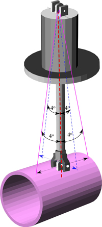
Designers must consider that the above support configurations all allow some movement depending upon the overall size, orientation, and configuration of the assembly. For example, hanger assemblies can accommodate translational motion producing swing angles of +/- 4 degrees maximum. This means that designers may be able to accommodate greater pipe movement by incorporating longer support assemblies into the design, rather than introducing additional support components.
When active and passive support assemblies, comprised of standard components, cannot meet specific system requirements, designers can add auxiliary components, which are designed to extend the range of motion that these supports can accommodate during normal operation.
Auxiliary components
-
Travelers: Used to translate the forces exerted on hangers, a type of active support, across horizontal planes in conjunction with the movement of the pipe. Single horizontal travelers translate forces across one horizontal plane; dual horizontal travelers translate forces across two planes. Consist of rectangular box with a lug protruding from the center and are usually fastened between the structural steel and the rest of the pipe support assembly. Usually fabricated from carbon steel.
-
Rollers: Used to translate forces at the support location on the pipe to a new position in the piping system. Consist of a rolling mechanism attached to the active support component; the other end can either be in direct contact with the pipe or connected via a saddle attached to the pipe. Commonly fabricated of carbon steel; fabrication with polyurethane reduces the overall weight of the component.
-
Slide plates (slide bearing plates): Used to reduce friction associated with axial and lateral movements. The reduction in the friction forces helps reduce stresses on active support components during the pipe movement. Fabricated from carbon steel bonded to polytetrafluoroethylene (PTFE), 25% glass filled, for systems operating in environments cooler than 400 ºF. Can also use graphite, Bronzphite®, or marinite bonded to steel.
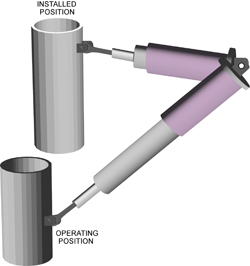
The following is an example illustrating the necessity of thoroughly reviewing all movements associated with pipe deflection during a given thermal cycle. In the initial (cold) position, a hydraulic snubber, attached both to stationary structural steel via an end bracket and to a pipe element via a three-bolt clamp, was installed at a cylinder position of 1 inch extension, with a total stroke available of 6 inches. An overall analysis indicated that the final operating (hot) position of the pipe would require that the snubber extend 4.5 inches (which could be accommodated by the remaining stroke of the hydraulic snubber cylinder).
After being put into service, the seals of the snubber were damaged, indicating that the cylinder, at some point, had been completely retracted or extended. Review of the pipe’s position indicated that it was correct according to the original design specifications.
However, a more thorough review of the pipe system revealed that, prior to reaching full operating conditions, the movement of the pipe created a condition in which the overall length of the snubber should have been reduced (retracted) by 1.5 inches. But, because the original set point of the snubber allowed a maximum of only 1 inch of contraction, the continued pipe movement stressed the snubber beyond its capabilites once it reached its fully contracted position (zero extension), thus damaging the support assembly.
To correct the problem, the original snubber was replaced with one that had an overall available stroke of 12 inches, allowing the initial set point to be increased to a cylinder position of 3 inches of extension. This new snubber design accommodated all pipe deflection throughout the entire process cycle.
Optimal use of pipe supports
• Become familiar with Manufacturers Standardization Society Standard Practices 58 and any other industry- or company-specific codes that apply to your project, such as American Society of Mechanical Engineers B31.1 for power and B31.3 for process engineering (both of which refer to MSS SP-58). The manufacturer and installation team should also be familiar with these standards and how to accommodate any specific requirements that apply to your project.
• Collect and use good data: Know the full range of loads and movement the piping system will handle during a full operating cycle, and remember that movement in the real world occurs in all three dimensions.
• Make note of other factors that can affect piping loads, such as temperature, weight, states of matter, and external conditions.