|
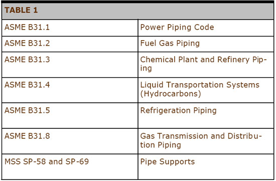
Piping systems are used to transport gases, liquids and suspended solids between units of a plant. The temperatures of the contents and the pipe when the plant is in operation are often quite different from the ambient temperature of the surroundings. The heat transferred during changes in temperature causes metal pipe to expand and contract. Piping designers must provide for movement due to temperature changes and forces caused by pumps, gravity and other elements of the piping system. Proven engineering practices are included in various codes for piping services developed by professional societies such as the American Society of Mechanical Engineers. Most companies use these codes to develop specific standards for their products. The Manufacturers’ Standardization Society has developed standards for pipe supports. Designs which satisfy codes are important to satisfy laws and to obtain financing and insurance for projects. Table 1 provides a list of some important standards.
|
|
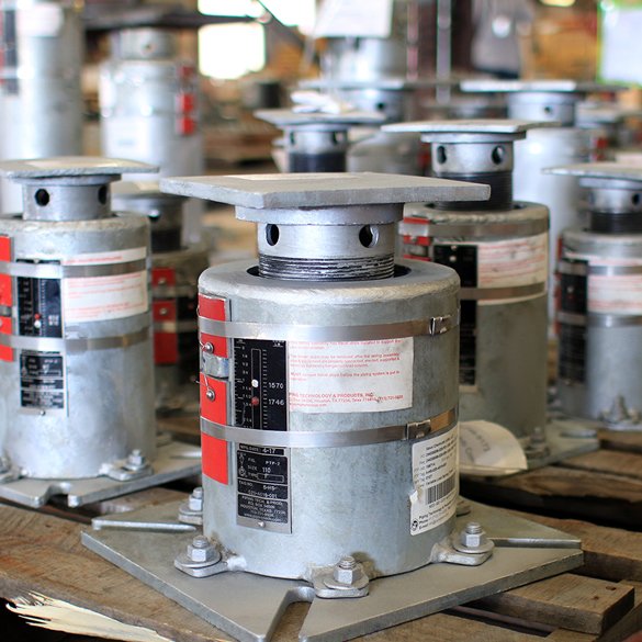
Variable springs are one of the most important devices available to help support pipe. They are used to balance the concentrated gravitational load of vertical sections of pipe while allowing for thermal movement. Control of the direction and amount of movement of various sections of pipe is a major function of piping design. Computer models are used during design to predict the forces and movement at the point where a spring support is attached to the pipe. This is the information required to select the least expensive variable spring to use. Variable springs are relatively inexpensive and very reliable. When replacement is necessary, the engineer needs to determine if the original size is still appropriate or if the system has changed and different forces and movement must be considered.
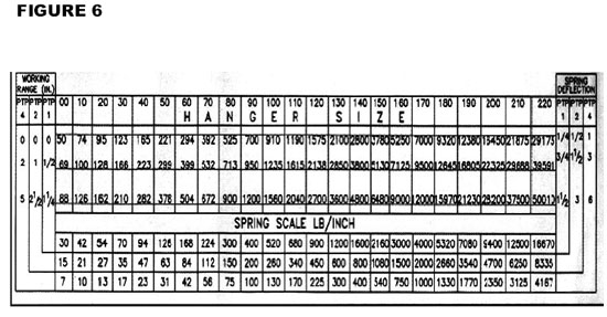
Pipe support manufacturers product catalogs which describe the items they routinely supply. The engineered spring support section of our catalog contains detailed information on variable springs. The load and travel tables contain the information required to size variable springs. An abbreviated version of this table is given in Figure 6. |
|
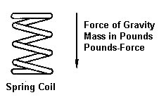
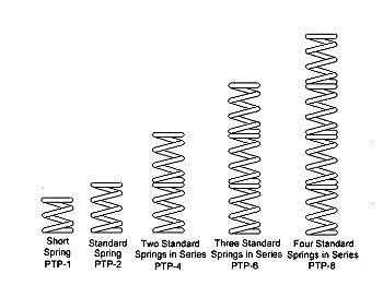
Variable spring supports are attached to piping systems so the coil is in a vertical position as shown in Figure 1. Forces which compress the coil act in the same direction as the force of gravity. Movement due to temperature changes may be either up or down. Movement is a vector which has both direction (up or down) and magnitude. Travel is a scaler which describes the length of movement or compression of the spring coil. A spring can only be compressed so much before the individual coils come together and it “goes solid”. The usual method used to provide for larger travel is to provide a longer coil or stack standard coils together as shown in Figure 2.
|
|
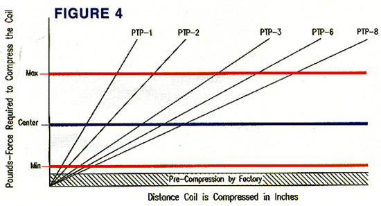
Newton’s Third Law of Motion states that every force is accompanied by an equal and opposite force. A spring coil resists the force which compresses it. The more the coil is compressed, the greater resistance it has to further compression. This is why pipe supports which apply forces directly to the spring coil are called variables. The magnitude of the force required to compress a spring coil depends on the size of the wire used to form the coil and on the diameter of the coil. A “stronger” coil can be produced by using a larger wire or by winding the wire “tighter”. The two industry standards are the PTP-1 (short spring) and the PTP-2 standard spring. Twenty-three different wire sizes from .23 inches to 2.5 inches are used to increase the size of the force required to compress the coil. At PT&P, we use 00, 10,…,200, 210, 220 to designate the wire size (resistance to force) of the coil as shown in the top of Figure 6. Figure 3 shows a graph of pounds-force required to compress a PTP-2, size 90 coil as a function of the amount of compression. The graph is a straight line through the origin with a slope of 200 pounds-force per inch of compression. The slope of this line is the spring rate of this variable support. We compress the coil three inches during assembly (using 600 pound-force). The variable produced can be further compressed an additional 3.5 inches (range of deflection) by applying 1300 pounds-force. Each additional 200 pounds-force will compress the coil one inch. 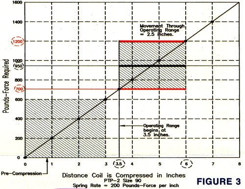 |
|
Manufacturers recommend that only 80% of the range of deflection (called the operating range) be used for variables. The PT&P load and travel table uses red lines to enclose the loads in the operating range. Figure 3 marks both the minimum and maximum loads (700 and 1200 pounds-foce) for the operating range with red lines. The load at the center of the operating range (950 pounds-force) is marked with a blue line. The total compression of the coil at 700 pounds-force is 3.5 inches and the compression at 1200 pounds-force is 6.0 inches so the operating range is 2.5 inches. Figure 6 show how to obtain these values from the load and travel table of our catalog.
 |
|
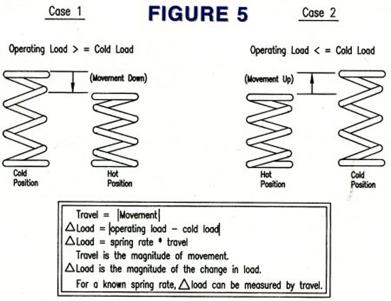
Selecting the Proper Size for a Variable The coil size (force required for compression) should be chosen to balance the expected force on the support when the system is operating. To do this, choose the size (00 to 220) which has its center compressive force (blue line) in Figure 6 as close as possible to the Operating Load (“hot load”). Choose the shortest (least expensive) coil and operating range which will satisfy the expected movement the support will experience during the temperature changes expected going from cold load (non-operating force applied) to operating load. Figure 5 illustrates the relation between the three quantities, operating load, cold load and movement. The direction of movement is defined by the change of load (force on the support) when the system changes from cold to operating. If the operating load is greater, the increase in the force will further compress the coil so the direction of the movement is down. If the operating load is smaller, the decrease in the force on the support will allow the coil to expand so the movement is up.
|
|
Variability Constraint The change in the force on the suport when changing from cold to operating is equal to the spring rate multiplied by the Travel (magnitude of the movement). Good practice as specified in MSS code requires that this change experienced by the support should be nom ore than 25% of the operating load, thus the inequality in Equation (a) must always be satisfied. Note that the spring rate is a function of both the coil size (Z) and the coil length (X). Coil size Z is chosen to match the operating load, so X is chosen as small as possible to satisfy Equation (a). The possible values of X are 1,2,4,6, and 8 which correspond to PTP-X and define the operating range of the support. (a) Spring Rate (Z,X) * Travel < 0.25 * Operating Load
If you are interested in a computer program that will size variable spring supports shown in the PT&P catalog, you can download here. |