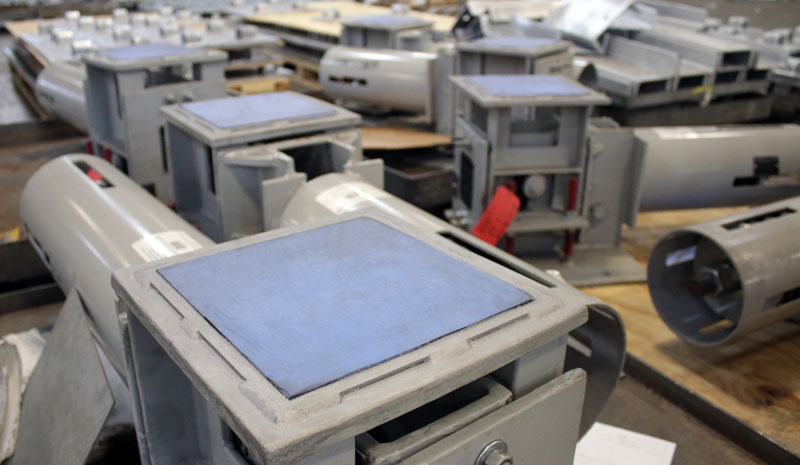
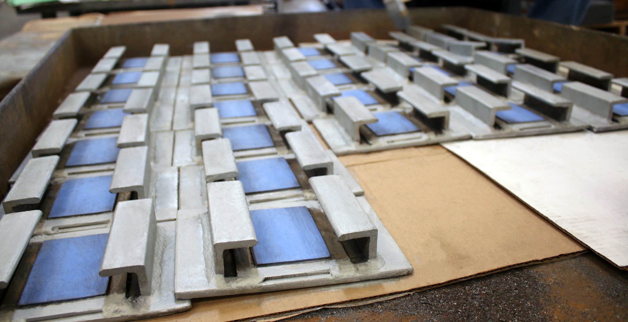
PTFE, 25% Glass Filled Slide Plates

PTFE, 25% glass filled slide plates are primarily used in low heat and high velocity conditions; however, this material can be used in high heat applications in conjunction with other materials. We also use this type of slide plate where there is high wear resistance, no surface treatments necessary or is unaffected by weather conditions.

Types & Sizes

Technical Information

Installation & Maintenance

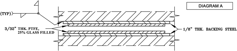
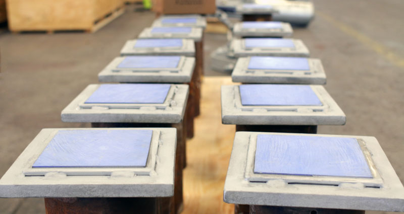
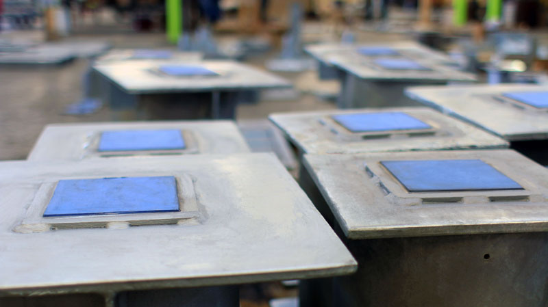
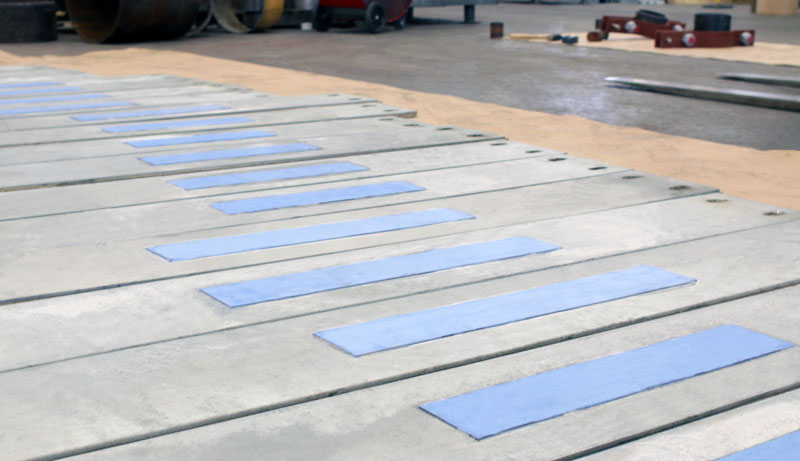
Prior to Welding: Locate the slide plate base in the appropriate position on the existing steel surface. Place a protective covering on the PTFE, 25% glass filled. Where seal welding is not required, follow the diagram shown which indicates 1/8” thick fillet weld, 1” long every 4” around the entire perimeter of the base. For welding, use GMAW 0.035 wire or SMAW 3/32″ stick.

Where full seal welding is required, use a similar pattern of welding until a full weld is obtained. This method will prevent damage to the PTFE, 25% glass filled. (A full weld will help prevent seepage of water between the slide bearing plate and the support structure.) Avoid overheating, which may destroy the bonding of the PTFE, 25% glass filled to the base plate.


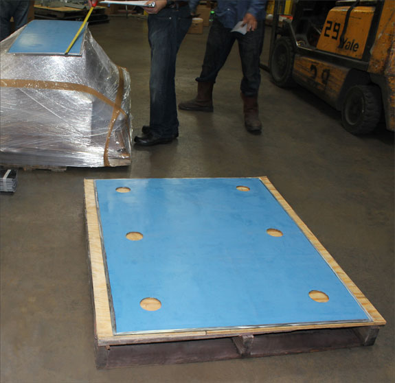
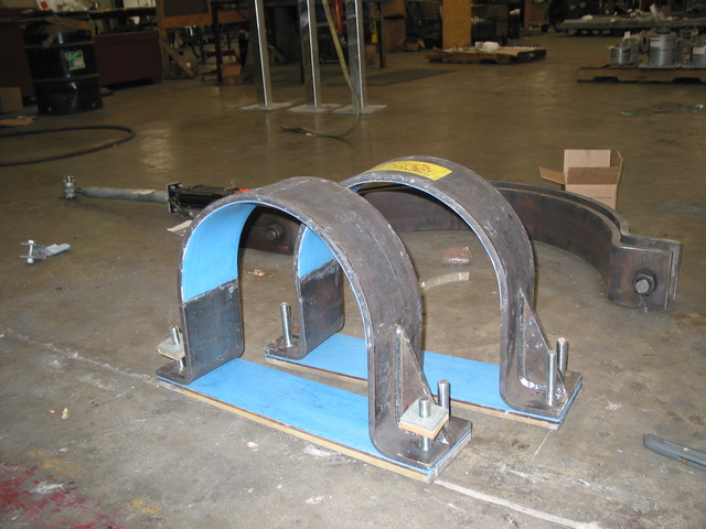
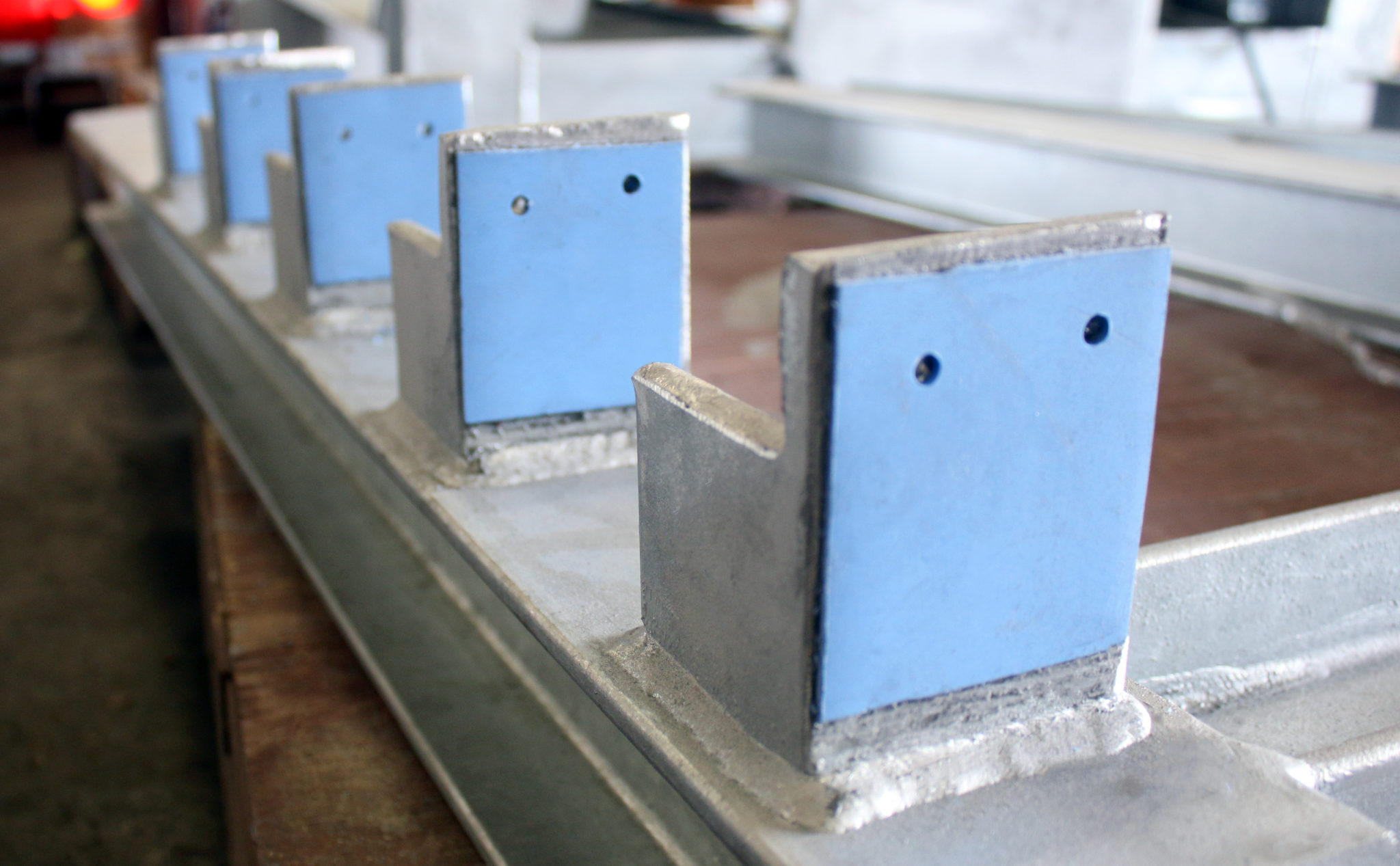
Installation in Concrete: When installing PTFE, 25% Glass Filled Slide Plate assemblies in concrete, anchor bolts will be integrated into the base plates for attachment to either the concrete form rebar structure or simply within the concrete itself.

Slide Plate Installation and Maintenance Guide

Case Studies

Request a Quote


When designing support systems for extreme structural loads and thermal movement, a standard resting surface is often insufficient. By incorporating a 25% glass-filled PTFE plate, we reinforce standard virgin PTFE with glass fibers, creating a support interface with significantly higher compressive strength and wear resistance. This ensures that every PTFE slide plate maintains long-term structural integrity without deforming or exhibiting “cold flow” under heavy operational demands

Whether your application requires a complete, custom-engineered Teflon® slide plate assembly or standard PTFE slide plates, our solutions are designed to effectively reduce friction and prevent mechanical failure.

By installing our high-performance Teflon® slide plates or using a single Teflon® sliding plate at critical structural junctions, your piping infrastructure can safely expand and contract.


See More Images

PTFE Slide Plate Inspection and Maintenance

Follow these steps when inspecting and maintaining PTFE slide plates. Inspect welds between backing plate and bottom of the saddle …Continue Reading

See More Videos

Q: What is the benefit of adding 25% glass to a PTFE plate? 

A: Adding 25% glass fibers to a standard PTFE plate significantly increases its compressive strength, lowers its tendency to deform under heavy loads (cold flow), and improves overall wear resistance compared to virgin PTFE.

Q: How does a glass-filled PTFE slide plate handle thermal movement?

A: A glass-filled PTFE slide plate provides an incredibly low-friction surface, allowing heavy piping systems to smoothly glide back and forth as they expand and contract from thermal changes, eliminating dangerous frictional stress.

Q: Are Teflon® slide plates capable of supporting heavy, large-bore piping? 

A: Yes. When properly bonded to a rigid steel backing, glass-reinforced Teflon® slide plates can withstand immense vertical compressive loads from large-bore piping without failing in structure.

Q: How is a Teflon® slide plate assembly typically installed? 

A: A complete Teflon® slide plate assembly usually consists of an upper polished stainless steel plate welded to the moving pipe shoe, which slides seamlessly against the lower glass-filled PTFE component with a backing plate that is securely mounted to the stationary structural steel foundation.

Q: Can I use a single Teflon® sliding plate for high-temperature applications?

A: While a Teflon® sliding plate is highly durable and chemically inert, it generally has a maximum continuous operating temperature of around 400°F. For pipes exceeding this temperature, structural insulation (like a hot shoe) is placed between the hot pipe and the sliding surface to protect the PTFE material.

Q: Do PTFE slide plates require regular lubrication or maintenance? 

A: No. One of the main operational advantages of using PTFE slide plates is that the material is naturally self-lubricating, completely eliminating the need for manual greasing even in harsh, inaccessible industrial environments.

More FAQs…

PTFE Standard Assembly

Download PTFE, 25%  PDF


Slide Plate – PTFE Diagram A

ASSEMBLY:

Standard Assembly
2 units of 3/32″ PTFE, 25% glass filled, bonded to 1/8″ carbon steel. For field tack welding. 1/2″ lip. Loads to 2000 PSI, Temperature: -320°F to +500°F


Full Weld Assembly:
2 units of 3/32″ PTFE, 25% glass filled, bonded to indicated backing material with 1/2″ lip all around for full welding. Loads to 2000 PSI, Temperature: -320°F to +500°F
PART # — PTP — 3/32″ TFE — 10 Ga. SS — 1/2″ LIP AND SIZE

ORDERING:

  • Please specify the dimensions of the upper plate and dimensions of the lower plate. It is common practice that the upper plate is generally larger than the lower plate.
  • Specify lip dimension (if different than the standard 1/2″).
  • Specify base plate thickness (if different than standard 1/8″).


ADVANTAGES:

  • Ease of installation.
  • No setting problems.
  • Low coefficient of friction.
  • No surface treatments, grouting, or expensive mechanical attachment necessary.
  • Chemically inert.
  • Unaffected by weather conditions.
  • Ability to absorb dirt and grit within itself.
  • Self-aligning when used in conjunction with elastomeric backing pads.


APPLICATIONS:

  • Bridges: Highway bridges, overpasses, railroad bridges.
  • Architectural in Wood, Concrete or Steel: Cross beam and girder slip joints, roof slabs and corbels, vibration pads, airport hangar doors, domes.
  • Industrial: Heat exchangers, dust collectors, heavy machinery, refinery equipment, wind tunnels, penstocks, vessels, pipelines, air preheaters, atomic energy applications, transmission towers, storage tanks, offshore drilling rigs.

Effect Of Temperature

Pg168

It has been determined from basic testing that the “ideal” thickness of PTFE, 25% Glass Filled, should be 3/32”. If the design engineer follows the given chart (left) for the Effect of Temperature on PTFE, 25% Glass Filled, there will not be a failure.

Coefficient Of Friction

Diagram b

The Coefficient of Friction of PTFE, 25% Glass Filled, slide plates has been reported to be from 0.01 to 0.2. This depends on the surface preparation, loading, velocity, and the duration of the test. Bonding PTFE, 25% Glass Filled, to metal increases the load capabilities in excess of 2,000 PSI (For design purposes, use 500 PSI). This table shows the coefficient of friction due to the load applied. A maximum coefficient of 0.1 can be used in PTFE, 25% Glass Filled, slide bearing designs without considering sliding speed, temperature, or maintenance.

Specification

PropertyValueASTM Test Method
MechanicalSpecific Gravity Measured2.1-2.3D638
Water Absorption (%)0.013D570-59T
Hardness, Shore D
@ 78°F
@ 300°F
57
56
D2240
Wear Factor KLess than 10 x 10-10
Tensile Strength (PSI)2,000 min.D1457-56T
Tensile Elongation200 - 250D1457-56T
Flexural Strength (PSI)606D790-59T
Modules (PSI)2.93 x 10⁵D638
Compressive Strength (PSI)
0.2% offest
1870D790-59T
Deformation at 78°F, 200 PSI
24 hr.
Permanent Deformation (%)
7.1
3.9
D621-59 (modified)
Deformation at 78°F, 200 PSI
100 hr.
Permanent Deformation (%)
8.9
4.4
Coefficient of Friction0.06 for loads
> 500 PSI static
Modified
ElectricalDielectrical Strength in air (v per mil)327D149A
Dielectrical Constant @ 60 cps2.63D150-54T
Volume Resistivity (ohm-cm)1013D257-57T
ThermalCoefficient of Linear Thermal Expansion (per °F)6.89 x 10⁻⁵D694-44
Coefficient of Thermal Expansion Conductivity (Btu-In.) hr-sq. (ft. °F)3.12Cenco-Fitch
Continuous Service Temperature550Various
WeatherabilityUnaffectedPhysical exposure

Download PTFE, 25% PDF

Top