Custom Sway Braces Designed for Coker Units

July 25, 2023


Sway Braces Custom Designed For Coker Units At An Oil Refinery In The Virgin Islands


Type: Custom Sway Braces with Ball Joints
Material: A36 Carbon Steel | Hot-dipped Galvanized
Testing: Standard Load Testing & Q.C. Inspection

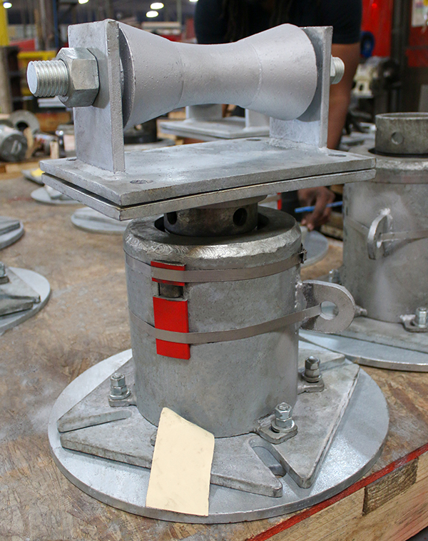
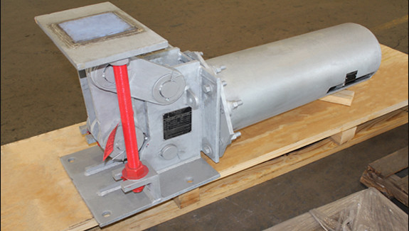
PT&P custom-designed sway braces on an urgent basis to replace existing sway braces at one of the ten largest oil refineries in the world initially built over 75 years ago. These sway braces will be used in Coker units that have long displacements. They are fabricated with “ball joints” at both ends due to the “banana effect,” where the Coker unit will actually bend due to the heating of one side of the Coker unit faster than the opposite side. The casing, pipe, coils, threaded rods, turnbuckle, ball joints, etc., are all fabricated from carbon steel with a hot-dipped galvanized finish.

The maximum loads, spring rates and movements for the sway braces are as follows:

Max Load (lb) Spring Rate (lb/in) Max Movement (+ / – in)
2475 90 10″
3800 267 3-3/4″
3480 120 9″
2500 200 2″

Learn more about our sway brace products and place an order with us today!

PT&P REF. ORIGINAL POST 03102020

Read More

F-Type Variable Springs with Rollers

July 18, 2023


F-Type Variable Spring Support &Amp; Pipe Roller Assemblies Designed For A Fabrication Company In Texas

Type: Variable Springs w/ Rollers
Size: Springs: 11.1/16″ H | Rollers: 24″ -36″ Dia.
Design: 700-15,970 lb. Loads | 650°F Temp.
Material: HDG Carbon Steel | Cast-iron
Testing: Standard Load Testing & Q.C. Inspection

Variables use coiled springs to support a load and allow movement. The resistance of the coil to a load changes during compression, which is why these devices are called “variables”. We offer a variety of different designs of variable spring pipe supports. View Variable Spring Supports Product Section.
For this application, the variable spring with rollers were used in natural gas compressor stations in Texas. Compressor stations are an essential part of a natural gas pipeline that moves natural gas from one location to another. At these stations, natural gas is re-pressurized and sent back into the pipeline system where it travels until the next compressor station. The location and distance between compressor stations is dependent on terrain, and the number of gas wells in the vicinity. Frequent elevation changes and a greater number of gas wells will require more compressor stations.
The compressor station, also called a pumping station, is the “engine” that powers a long-distance natural gas pipeline. As the name implies, the station compresses the gas (increasing its pressure) thereby providing energy to move it through the pipeline. The compressor is driven by a motor fueled by some of the natural gas bled from the pipeline. The size of the station and the number of compressors (pumps) varies, based on the diameter of the pipe and the volume of gas to be moved.
Piping Technology and Products and its subsidiaries provide products and services to this critical piece of the energy infrastructure with not only variable spring supports with rollers showcased here, but also with insulated supports, expansion joints, pipe shoes, guides, and anchors.


PT&P REF. ORIGINAL POST 02172020

Read More

U-Type Constants Designed with Slide Plates for a Polypropylene Plant in Texas

July 4, 2023

147164A1

PT&P designed and fabricated a U-Type constant spring support , with PTFE and a 25% glass-filled side plate for a Polypropylene Plant in Texas. The constant is fabricated from carbon steel and hot-dipped galvanized for extra protection against corrosion. The vertical movement is 1.5" total upward travel and is capable of supporting a load of 10,350 lbs. throughout its range of movement. The constant underwent standard load testing prior to shipment.

Along with chemical plants, constant spring supports are utilized in refineries, power plants, and heat recovery steam generators (HRSG). The design of the constant spring support replaced a system of pipe support called a "counterweight" design still used in some facilities today. The counter-weight system utilized pipe clamps or lugs (attached or welded to the pipe), cables, pulleys, and a set of weights. Just like the old-fashioned brass weighing scales, weights were added to one end of the pulley system until an equilibrium was reached. The counterweight design needed a large amount of space with which to operate. Constant spring hangers replaced this system because they require much less space in order to function (similar to some designs we stand on to weigh ourselves). No matter the application, our team of experienced engineers and designers can help to resolve your pipe support needs. Please contact us via our 24×7 emergency service or send an email to info@pipingtech.com.

PT&P REF. ORIGINAL POST 08232016

Read More
Top