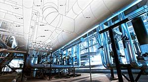
Liquefied Natural Gas (LNG) facilities in the United States operate under strict federal safety regulations that mandate effective containment of potential LNG spills. These requirements—enforced by the Federal Energy Regulatory Commission (FERC) and aligned with NFPA 59A (National Fire Protection Association Standard 59A)—are designed to ensure that LNG releases are controlled, safely directed, and prevented from damaging structural systems or endangering personnel.
Cryogenic fluids such as LNG present significant hazards during a spill event. Extreme temperature differentials can induce thermal shock, leading to brittle fracture of structural steel. In addition, conventional containment systems may fail under severe environmental conditions such as hurricane-force winds, sub-zero temperatures, and combined dynamic loads. These failures can result in uncontrolled LNG release, environmental impact, and damage to adjacent infrastructure.
A critical component of LNG facility safety and compliance is pipe spill containment, typically achieved through the integration of:
- Troughs – linear containment systems installed beneath piping
- Shrouds – localized enclosures designed to manage vapor dispersion
This bulletin outlines the function, application, and engineering considerations of troughs and shrouds in cryogenic LNG systems.
Function of LNG Spill Containment Troughs
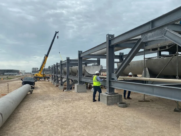
Trough systems are engineered to capture, contain, and safely channel LNG spills under cryogenic and high-wind conditions. These systems typically consist of modular, interconnected sections forming a continuous containment path beneath LNG piping systems such as rundown lines and condensate lines.
Each trough module is supported by guided and sliding structural elements that allow for thermal expansion and contraction, ensuring system integrity across extreme temperature ranges.
Key Functions
- Capture LNG in the event of a pipeline leak or spill
- Prevent direct contact between cryogenic liquid and structural steel
- Direct LNG to designated drainage or vaporization areas
- Minimize thermal shock to supporting structures
Typical Applications
LNG containment troughs are commonly used in:
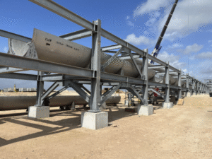
- Elevated pipe racks
- LNG transfer lines between process units
- LNG loading and unloading systems
- Areas requiring protection against brittle fracture of carbon steel structures
Engineering Considerations for LNG Trough Design
Due to LNG storage temperatures of approximately –260°F to –274°F, trough systems must be carefully engineered to withstand extreme conditions.
At Piping Technology & Products (PT&P), LNG trough systems are designed with the following considerations:
- High-Capacity Spill Handling
Designed to contain LNG spill flow rates up to 5,723,072 lb/hr - Thermal Expansion and Contraction
Engineered to accommodate temperature differentials from +150°F to –274°F, with controlled displacement through guided support systems - Wind Load Resistance
Designed to withstand Category V hurricane winds (up to 190 MPH), validated through Finite Element Analysis (FEA) - Structural Load and Reaction Forces
Detailed analysis of axial and lateral loads from wind, thermal movement, and LNG weight. High-load areas are reinforced with heavy-duty guides and structural supports - Material Selection for Cryogenic Service
Materials are selected to maintain strength and toughness at extremely low temperatures - Compatibility with Pipe Movement
Ensures trough systems do not restrict thermal movement of process piping - Drainage Design
Optimized slope and flow control to safely route LNG to containment or vaporization zones
These design factors ensure that trough systems perform reliably during spill events without overloading supporting structures.
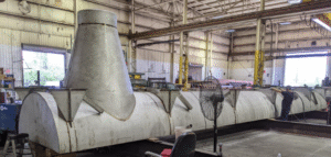
Function of LNG Vapor Dispersion Shrouds
Shrouds are localized protective enclosures installed around or above LNG piping to manage vapor dispersion in the event of a leak. Their primary function is to contain and direct cold vapor clouds, reducing the risk of exposure to surrounding equipment and personnel.
Key Functions
- Control and limit LNG vapor dispersion
- Protect nearby structural components from cryogenic exposure
- Reduce risk of vapor cloud spread in critical areas
Engineering Considerations for Shrouds
Effective shroud design requires careful attention to:
- Cryogenic Compatibility – Materials must withstand extreme low temperatures without embrittlement
- Wind and Structural Loads – Designed to resist environmental forces without deformation
- Ventilation and Vapor Management – Proper airflow to safely disperse vapor without pressure buildup
- Non-Restrictive Design – Must allow full thermal movement of piping systems
- Structural Integration – Seamless integration with pipe racks and support systems
Conclusion
In LNG pipeline systems, troughs and shrouds play complementary roles in spill containment and vapor control.
- Troughs provide continuous collection and controlled routing of liquid LNG spills
- Shrouds manage localized vapor dispersion and protect surrounding infrastructure
Both systems must be engineered to accommodate cryogenic temperatures, structural loads, and piping movement while meeting stringent regulatory requirements.
Proper design and integration of LNG spill containment systems not only ensure compliance with FERC and NFPA 59A, but also significantly enhance overall facility safety and reliability.
Early engineering involvement is critical to developing effective, compliant, and durable containment solutions for LNG facilities.
Schedule a meeting with our engineers to discuss your expansion joint protection needs.